Relative orbit attitude finite time control method for non-cooperative target spacecraft

A non-cooperative target and relative orbit technology, applied in attitude control, three-dimensional position/course control, non-electric variable control, etc., can solve problems such as complex dynamic model and complex controller form, and achieve easy engineering implementation and simple form , the effect of small amount of calculation

Active Publication Date: 2016-02-24
HARBIN INST OF TECH
View PDF5 Cites 21 Cited by
  • Summary
  • Abstract
  • Description
  • Claims
  • Application Information

AI Technical Summary

Problems solved by technology

[0077] In this scheme, the dynamics model used is relatively complicated, and the form of the controller is relatively complicated. It is still an asymptotically stable system. Theoretically, under the action of this controller, the tracking spacecraft fails to reach balance point of the system

Method used


Image

  • Relative orbit attitude finite time control method for non-cooperative target spacecraft
  • Relative orbit attitude finite time control method for non-cooperative target spacecraft
  • Relative orbit attitude finite time control method for non-cooperative target spacecraft

Examples


specific Embodiment approach 1

[0093] DETAILED DESCRIPTION OF THE PREFERRED EMBODIMENT 1. A non-cooperative target spacecraft relative orbital attitude finite time control method described in this specific embodiment includes the following steps:

[0094] Step 1. Project the relative orbital dynamics model represented by the inertial system to the line of sight system, and use the line of sight system to describe the relative orbital dynamics model of the spacecraft;

[0095] Step 2, establishing attitude dynamics model and attitude kinematics model;

[0096] Step 3, performing state space representation on the relative orbital dynamics model, attitude dynamics model and attitude kinematics model to obtain the relative orbital attitude dynamics model;

[0097] Step 4: Obtain a finite-time continuous controller based on the relative orbital attitude dynamics model and finite-time control theory.

[0098]This embodiment adopts the finite-time control theory and adopts the continuous control method to obtain ...

specific Embodiment approach 2

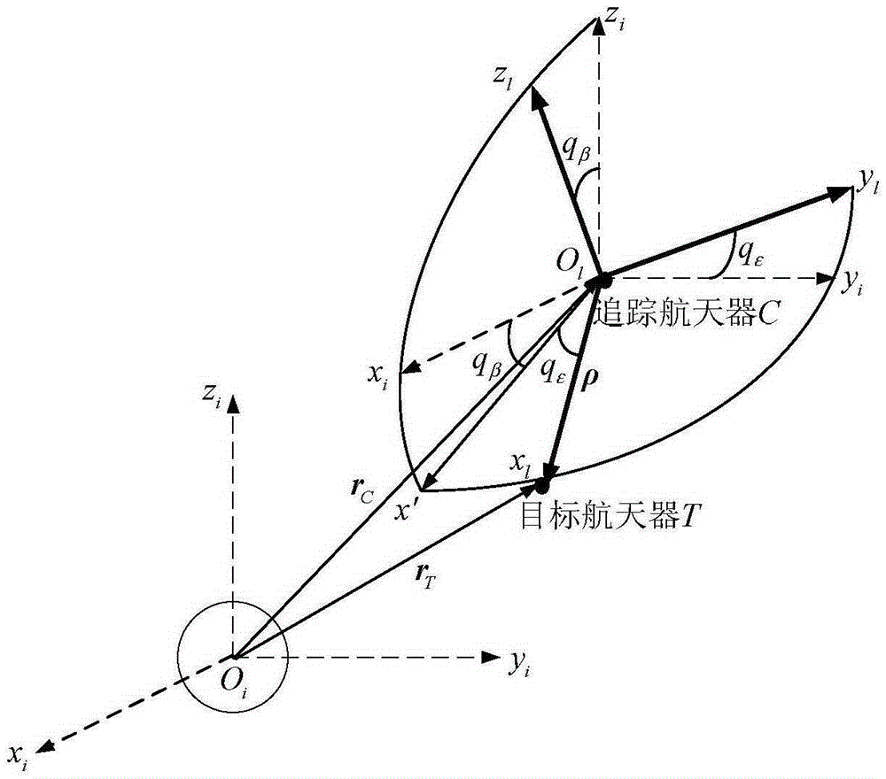
[0099] Specific embodiment two, combine figure 1 Describe this specific embodiment. The difference between this specific embodiment and the finite-time control method for the relative orbital attitude of a non-cooperative target spacecraft described in the first specific embodiment is that the relative orbital dynamics expressed by the inertial system described in the first step The specific process of using the line-of-sight system to describe the relative orbital dynamics model of the spacecraft is as follows:

[0100] will use the inertial frame O i x i the y i z i The relative orbital dynamics model represented by is projected to the line of sight O l x l the y l z l :

[0101] ( d 2 ρ ...

specific Embodiment approach 3

[0106] Specific Embodiment Three. The difference between this specific embodiment and the finite-time control method for the relative orbital attitude of a non-cooperative target spacecraft described in the second specific embodiment is that the establishment of the attitude dynamics model and the attitude kinematics model described in step two The specific process is:

[0107] Use the subscript b to represent the body coordinate system, t to represent the target aircraft, and c to represent the tracking aircraft, then the attitude dynamics equation of the tracking spacecraft, that is, the attitude dynamics model is:

[0108] J c ω · b c + ω b c × J c ω b c = ...


PUM


Abstract

The invention discloses a relative orbit attitude finite time control method for a non-cooperative target spacecraft, and relates to the field of aerospace. The method solves the problems in present relative orbit attitude joint control of non-cooperative target spacecrafts. The relative orbit attitude finite time control method for the non-cooperative target spacecraft comprises the following steps: 1, projecting a relative orbit dynamics model expressed by an inertial system to a sight system, and describing the relative orbit dynamics model of the spacecraft by adopting the sight system; 2, establishing an attitude dynamics model and an attitude kinematics model; 3, performing state space representation on the relative orbit dynamics model, the attitude dynamics model and the attitude kinematics model to obtain a relative orbit attitude dynamics model; and 4, obtaining a finite time continuous controller according to the relative orbit attitude dynamics model and the finite time control theory. The method is suitable for relative orbit attitude joint control of non-cooperative target spacecrafts.

Description

technical field [0001] The invention relates to the field of aerospace. Background technique [0002] With the development and utilization of space resources, various countries have launched their own satellites and built their own space stations, but as the number of satellites and space stations continues to increase, space resources are becoming more and more scarce, and due to the lifespan or failure of satellites, A large amount of space junk has been produced, occupying a lot of orbital resources. For this reason, space tasks such as approaching and close-range tracking and monitoring of non-cooperative targets such as space debris and failed satellites, and maintaining failed spacecraft to restore them to work have become a research hotspot and difficulty in the aerospace field today. Although the goals of these space missions are various, they all have the same requirement, that is, the orbit and attitude of the spacecraft can reach the desired state with high contr...

Claims


Application Information

Patent Timeline
Patent Type & Authority Applications(China)
IPC IPC(8): G05D1/08G05D1/10
CPCB64G1/244G05D1/101
Inventor 龚有敏孙延超马广富耿远卓凌惠祥李传江
Owner HARBIN INST OF TECH
Why Eureka
Try Eureka