A Broadband Array Antenna
An array antenna and array technology, which is applied in the direction of antenna, antenna grounding switch structure connection, combination of antenna units with different polarization directions, etc., can solve the problem of limited system communication capacity improvement, affecting the transmission rate of communication system, and large overlapping area of adjacent cells. and other problems, to achieve the effect of reducing operation and maintenance costs, reducing the number of antennas, and fast beam convergence capability.
- Summary
- Abstract
- Description
- Claims
- Application Information
AI Technical Summary
Problems solved by technology
Method used
Image
Examples
Embodiment 1
[0029] Such as figure 2 with 3 As shown, a wide-band array antenna provided by an embodiment of the present invention includes a metal reflector, a horizontal power distribution network installed on the metal reflector, an oscillator fixed on the horizontal power distribution network, and a vertical power division phase shifting network.
[0030] The radiating element array includes at least one sub-array in the horizontal direction, and each sub-array includes a plurality of oscillators arranged in the horizontal direction;
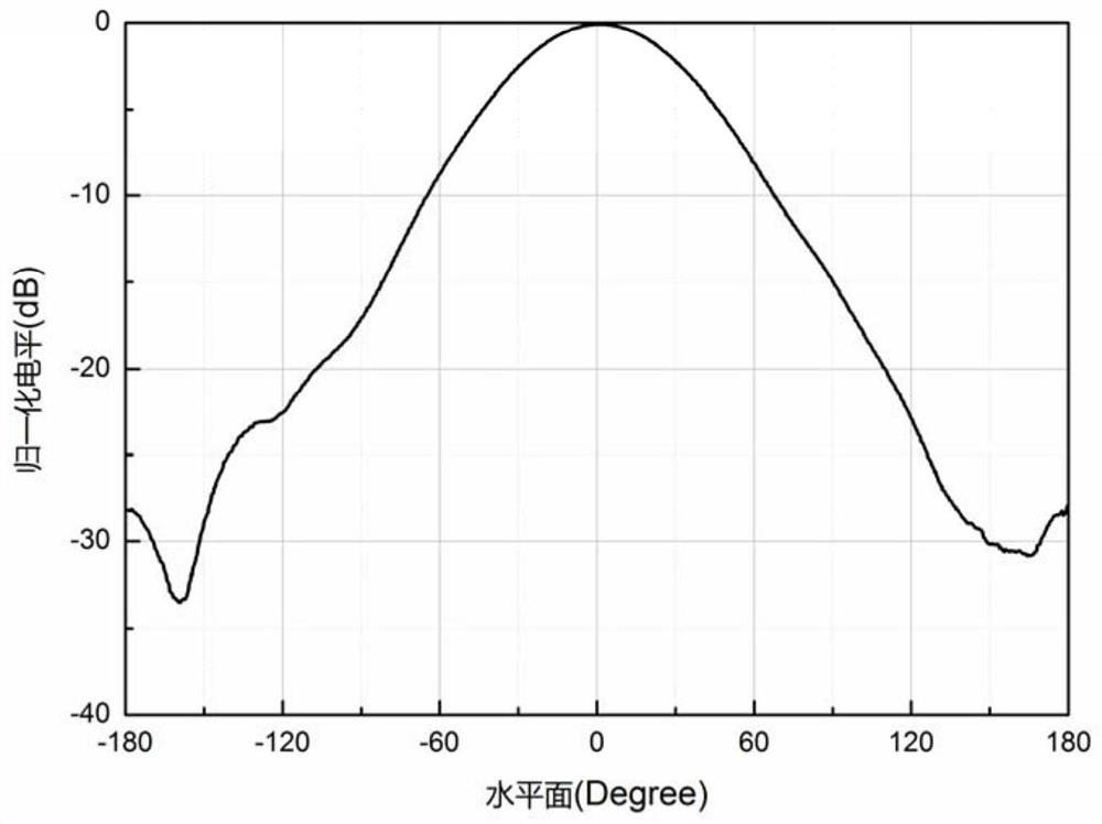
[0031] The horizontal plane pattern of the broadband array antenna is rectangular, the amplitude is stable within 3dB of the main beam direction and has at least 2 peaks, and the power drops rapidly outside the main beam range, and the 3dB to 20dB power drop angle is less than 25 degrees.
[0032] Preferably, the radiating element array is composed of 25 dual-polarized oscillators 101, the 25 oscillators are divided into 5 sub-arrays, and each sub-arr...
Embodiment 2
[0036] Such as Figure 5 As shown, the embodiment of the present invention is changed on the basis of the first embodiment.
[0037] The embodiment of the present invention provides a dual-band rectangular shaped antenna working at 1710-2200 MHz and 2300-2700 MHz. 111, 112 and 113 are respectively ±45 dual-polarized oscillator units operating in the 2300-2700MHz frequency band, a horizontal power distribution network, and a vertical power division phase-shifting network to form a 2300-2700MHz frequency band subsystem; the oscillator and feeder The connection of the network is the same as that in the first embodiment; the horizontal spacing of the oscillators is D1H, and the vertical spacing is D1V. 211, 212 and 213 are respectively ±45 dual-polarized oscillator units operating in the 1710-2200MHz frequency band, a horizontal power distribution network, and a vertical power division phase-shifting network to form a 1710-2200MHz frequency band subsystem; the oscillator and feed...
Embodiment 3
[0043] Such as Image 6 As shown, the embodiment of the present invention provides a three-band array antenna.
[0044] 116 in the figure is the dual-band antenna of the second embodiment, and the working frequency bands are 1710-2200 and 2300-2700 MHz respectively. 311, 312 and 313 are ±45 dual-polarization oscillators working in the 698-960MHz frequency band, horizontal power distribution network and vertical power division phase shifter network. The connection between the dual-polarization dipoles and the feed network is the same as in the first embodiment; the horizontal distance between the dipoles is D3H, and the vertical distance is D3V. The +45 polarization signal F3 of the 698-960MHz subsystem and the +45 polarization signal F1 of the 1710-2200 / 2300-2700MHz dual-band system are connected to the combiner 107 to form a shared output port G1; similarly, the The -45 polarization signal F4 of the 698-960MHz subsystem and the -45 polarization signal F2 of the 1710-2200 / 23...
PUM
 Abstract
Description
Claims
Application Information
 - R&D
- Intellectual Property
- Life Sciences
- Materials
- Tech Scout
- Unparalleled Data Quality
- Higher Quality Content
- 60% Fewer Hallucinations
Browse by: Latest US Patents, China's latest patents, Technical Efficacy Thesaurus, Application Domain, Technology Topic, Popular Technical Reports.
© 2025 PatSnap. All rights reserved.Legal|Privacy policy|Modern Slavery Act Transparency Statement|Sitemap|About US| Contact US: help@patsnap.com


