
Mechanical arm motion trail adjusting system and method

A technology of motion track and adjustment system, which is applied in the field of weld seam tracking, and can solve problems such as complicated programming, difficult welding, and heavy workload

Active Publication Date: 2016-03-02
广州中浩控制技术有限公司
View PDF9 Cites 13 Cited by
  • Summary
  • Abstract
  • Description
  • Claims
  • Application Information

AI Technical Summary

Problems solved by technology

However, in the actual operation process, sometimes it is necessary to use more types of robotic arms, and because of the different types of these robotic arms, during the real-time tracking process of the robotic arm, writing programs is complicated, and the codes written for each type of robotic arm are different. Generates a huge workload, causing great difficulties to the actual welding

Method used

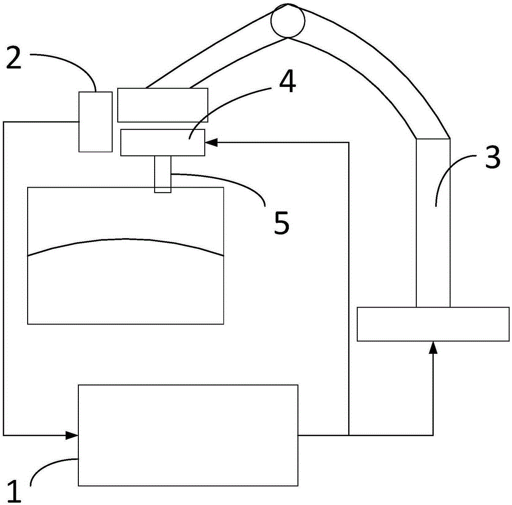

Image

  • Mechanical arm motion trail adjusting system and method
  • Mechanical arm motion trail adjusting system and method
  • Mechanical arm motion trail adjusting system and method

Examples


Embodiment 1

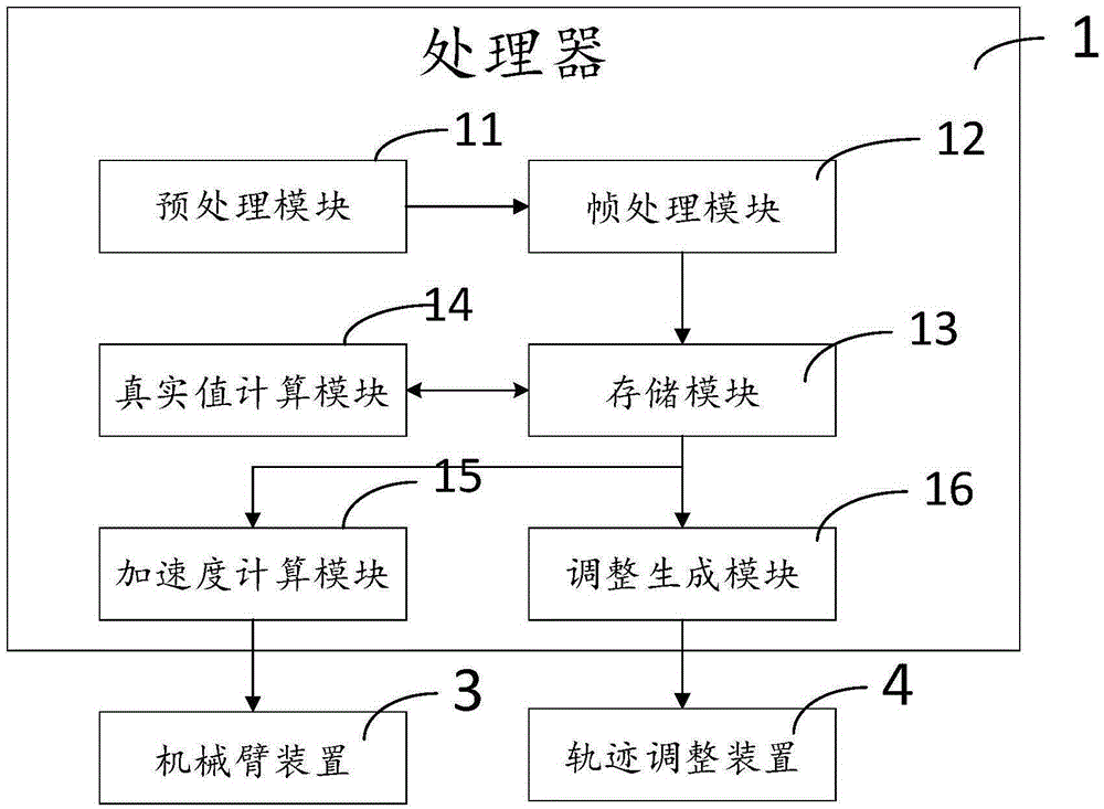
[0064] As described above, the motion track adjustment system of the mechanical arm, the present embodiment differs from it in that, as figure 2 As shown in the structure diagram of the processor of the robot arm motion track adjustment system of the present invention, the processor 1 includes: a preprocessing module 11, a frame processing module 12, a storage module 13, a real value calculation module 14, an acceleration calculation module 15 and an adjustment generation Module 16; the pre-processing module 11 receives the video image data, and sharpens each frame of image; the frame processing module 12 processes each frame of image after sharpening, and obtains the position of each position and the welding head of the welding torch 5 The measured value is also stored in the storage module 13; the real value calculation module 14 reads the measured value of the same position in different frame images from the storage module 13, calculates the real value of the position and s...

Embodiment 2

[0068] As described above, the motion trajectory adjustment system of the manipulator, the present embodiment is different from it in that the calculation formula of the real value calculation module 14 for the same position real value is:

[0069] Z = Σ i = 1 n B i Z i Σ i = 1 n B i

[0070] Among them, B i Determined by the following formula:

[0071] A i = Σ j = 1 n ...

Embodiment 3

[0079]As described above, the motion trajectory adjustment system of the manipulator, the present embodiment is different from it in that the formula for calculating the acceleration by the acceleration calculation module 15 is:

[0080] α i - = min { min s ≤ k i ( a i k ) , a }

[0081] Among them, a ik Determined by the following formula:

[0082] a i k = v i 2 - v k ...


PUM


Abstract

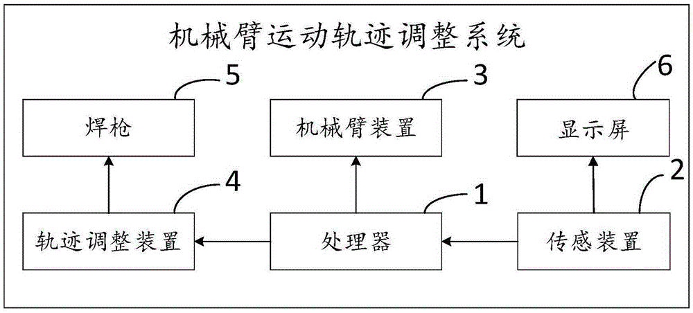
The invention provides a mechanical arm motion trail adjusting system and method. The system comprises a sensing device, a processor, a mechanical arm device, a trail adjusting device and a welding gun, wherein the sensing device is used for scanning a welded joint and a welding head of the welding gun; the processor receives scanned video image data and processes the data so as to obtain and send acceleration signals and trail adjusting signals; the mechanical arm device is guided by a user to move once along the welded joint on a welded joint plate to be used as a demonstration trail, and then repeats the demonstration trail according to the acceleration signals; the trail adjusting device receives the trail adjusting signals and slightly adjusts the position of the welding gun; the welding gun is used for welding the welded joint. The method corresponds to the system. In this way, the system and method are applied to large-scale mechanical arm cooperation, and huge workloads caused by the code difference between different types of mechanical arms are reduced; in a single mechanical arm, the welding precision can be improved by slightly adjusting the welding gun again on the basis of mechanical arm motion adjustment.

Description

technical field [0001] The invention relates to the technical field of seam tracking, in particular to a system and method for adjusting the motion track of a mechanical arm. Background technique [0002] The so-called seam tracking is to detect the deviation of the seam in real time during welding, and adjust the welding path and welding parameters to ensure the reliability of welding quality. Due to the machining errors of the workpieces (size differences between workpieces, preparation of grooves, etc.), clamping accuracy, and thermal deformation during welding, the welding manipulator often has deviations between the weld seam and the teaching track during welding. This leads to a decrease in welding quality. Therefore, seam tracking is an important aspect to ensure the welding quality of the robotic arm. [0003] The existing seam tracking generally means that the sensor detects the status of the seam in real time during the seam welding process, such as the size diff...

Claims


Application Information

Patent Timeline
IPC IPC(8): B23K9/127B25J9/16
CPCB23K9/127B25J9/1664
Inventor 蒋晓明毕齐林刘晓光赫亮
Owner 广州中浩控制技术有限公司
Learn More