Supercharge Your Innovation With Domain-Expert AI Agents!

Braking clamp for rail vehicle

A brake caliper, rail vehicle technology, applied in the direction of brake type, brake parts, axial brake, etc., can solve the problems of difficult assembly, unsafe, cumbersome maintenance, etc., to achieve easy assembly, simple structure, and maintenance simple effect

Active Publication Date: 2016-03-02
CRRC CHANGZHOU TECH MARK IND CO LTD +1
View PDF8 Cites 7 Cited by
  • Summary
  • Abstract
  • Description
  • Claims
  • Application Information

AI Technical Summary

Problems solved by technology

[0002] Most of the existing rail transit brake caliper adopts active brake caliper, this kind of caliper brakes through oil, and relieves oil discharge, but this kind of brake caliper cannot be completed once the oil circuit breaks down during the working process of the brake caliper. Braking is very unsafe; for passive brake calipers, that is, brake calipers with oil relief and oil release brakes, due to the limited energy storage stroke inside the brake calipers, a gap adjustment mechanism must be used, but for the brake calipers used in For brake calipers in high-speed environments, the traditional gap adjustment mechanism is prone to failure, and its complex internal structure also makes maintenance quite cumbersome. Moreover, the shape of the caliper body and the cylinder body of the passive caliper are relatively complicated and difficult to assemble. The production is also basically in the form of casting, and the strength is still low. It can only be used for braking in low-speed environments, and there will be deflection between the brake disc and the brake disc during use.

Method used


Image

  • Braking clamp for rail vehicle
  • Braking clamp for rail vehicle
  • Braking clamp for rail vehicle

Examples


Embodiment Construction

[0037] The present invention will be further described below in conjunction with the accompanying drawings and given embodiments.

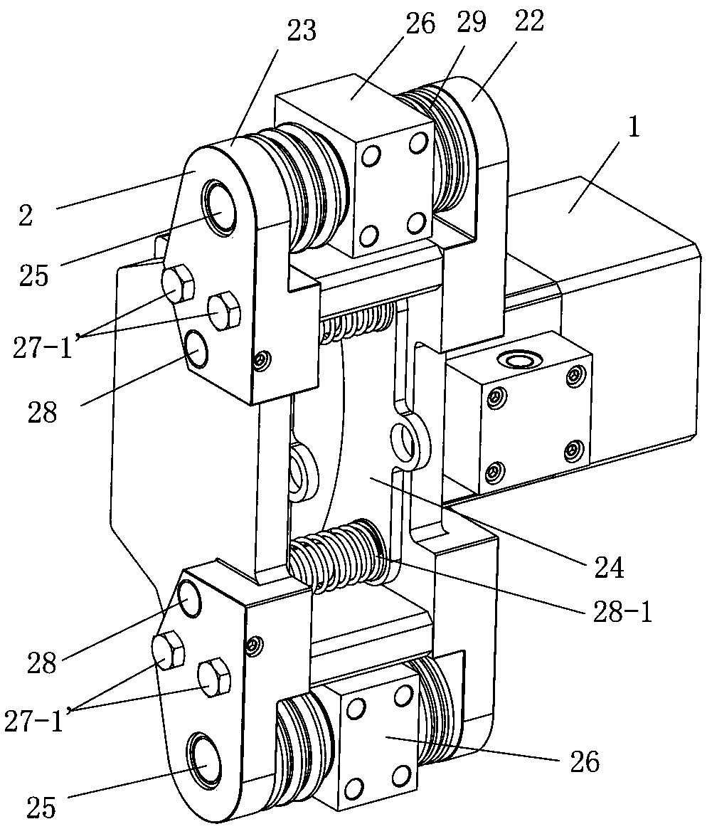
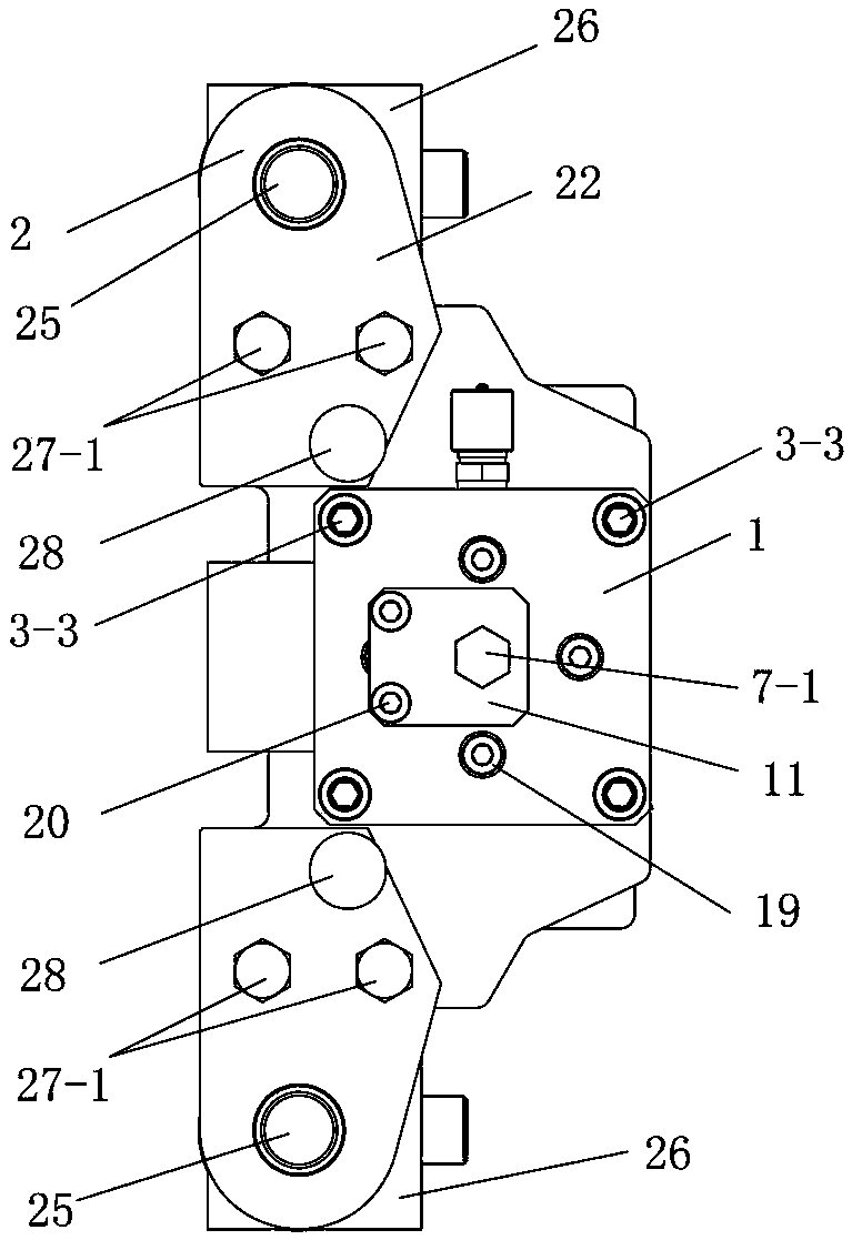
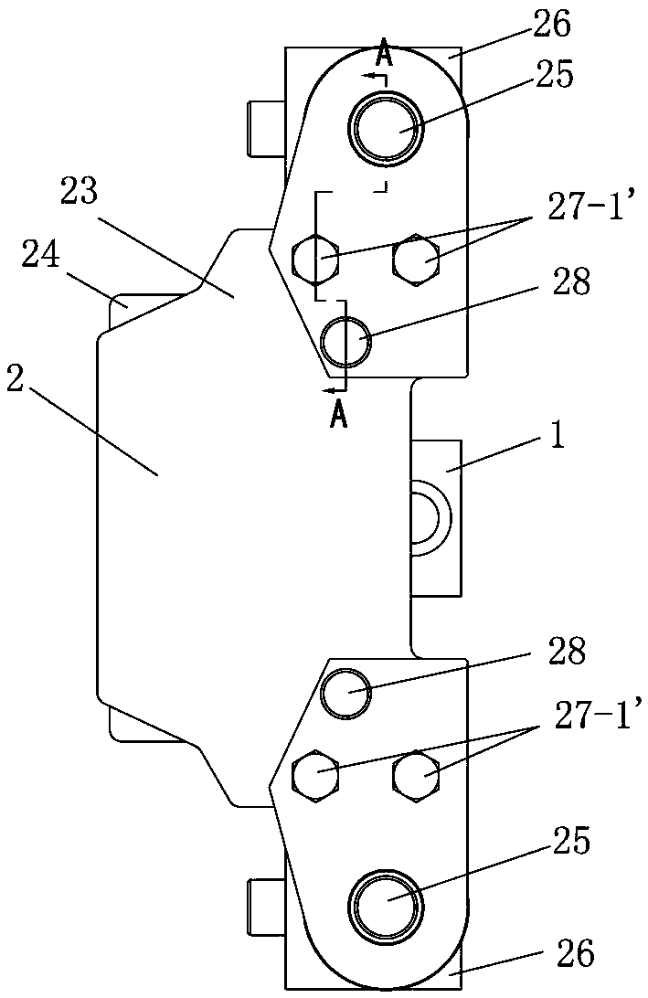
[0038] Such as Figure 1~12 As shown, a rail vehicle brake caliper has an oil cylinder 1 and a caliper body mechanism 2, the cylinder body 3 of the oil cylinder 1 includes a front cylinder body 3-1 and a rear cylinder body 3-2, and the front cylinder body 3- 1 and the rear cylinder 3-2 are axially connected, and the cylinder 3 is equipped with a piston 4, a reset piston 5, an adjustment shaft 6, a guide rod 7, a shaft sleeve 8, an elastic member 9 and a spring base 10.

[0039] The piston 4 is set on the reset piston 5, one end of the adjustment shaft 6 protrudes from the stepped hole 5-1 of the reset piston 5, and the other end is inserted into the sleeve hole 8-1 of the sleeve 8, and is connected with the sleeve 8 The shaft sleeve hole 8-1 is threaded, the shaft sleeve 8 is provided with an annular boss 8-2, and one side of the annular boss 8-2...


PUM


Abstract

Provided is a braking clamp for a rail vehicle. A cylinder body of an oil cylinder comprises a front cylinder body and a back cylinder body, and the front cylinder body and the back cylinder body are connectedly installed in the axial direction. A piston is installed on a resetting piston in a sleeving mode. One end of an adjusting shaft stretches out of a stepped hole of the resetting piston, and the other end of the adjusting shaft is inserted into a shaft sleeve hole of a shaft sleeve and is connected with the shaft sleeve hole of the shaft sleeve in a threaded mode. A clamp body mechanism comprises a first clamp body, a second clamp body, installing pin shafts, installing bases and supporting plates. The outside of the upper supporting plate and the outside of the lower supporting plate are further provided with the upper installing pin shaft and the lower installing pin shaft as well as an upper brake pad pin shaft and a lower brake pad pin shaft respectively. The brake pad pin shafts are installed on the first clamp body and the second clamp body in a limiting mode in the axial direction. The first clamp body is provided with a plurality of oil cylinder installing holes and an oil cylinder adjusting shaft through hole. According to the braking clamp for the rail vehicle, when oil is introduced, relieving is conducted, and when the oil is drained, braking is conducted, so that the braking clamp is safer; a manual clearance adjusting mechanism is arranged inside the oil cylinder, the structure is simple, malfunction is not prone to occurring, and the maintenance is very easy; parts of the clamp body mechanism are simple geometries, so that assembling is easy, the strength is high, and the condition of deflection between the parts of the clamp body mechanism and a brake disc is avoided.

Description

technical field [0001] The invention belongs to the technical field of foundation braking devices, and in particular relates to a brake caliper for rail vehicles. Background technique [0002] Most of the existing rail transit brake caliper adopts active brake caliper, this kind of caliper brakes through oil, and relieves oil discharge, but this kind of brake caliper cannot be completed once the oil circuit breaks down during the working process of the brake caliper. Braking is very unsafe; for passive brake calipers, that is, brake calipers with oil relief and oil release brakes, due to the limited energy storage stroke inside the brake calipers, a gap adjustment mechanism must be used, but for the brake calipers used in For brake calipers in high-speed environments, the traditional clearance adjustment mechanism is prone to failure, and its complex internal structure also makes maintenance quite cumbersome. Moreover, the shape of the body mechanism and the cylinder body of...

Claims


Application Information

Patent Timeline
Patent Type & Authority Applications(China)
IPC IPC(8): F16D65/22F16D55/225F16D65/092F16D121/06F16D125/04
Inventor 雷国伟苟青炳杜利清梅卓民王永胜
Owner CRRC CHANGZHOU TECH MARK IND CO LTD
Features
  • R&D
  • Intellectual Property
  • Life Sciences
  • Materials
  • Tech Scout
  • Unparalleled Data Quality
  • Higher Quality Content
  • 60% Fewer Hallucinations
Learn More