Chain type power transmission line single terminal fault location limited continuation method based on characteristic of fault traveling wave distribution along line

A technique for transmission lines, distributed characteristics, applied to fault locations, detection of faults by conductor type, measurement of electricity, etc.

Active Publication Date: 2016-03-02
KUNMING UNIV OF SCI & TECH
View PDF9 Cites 14 Cited by
  • Summary
  • Abstract
  • Description
  • Claims
  • Application Information

AI Technical Summary

Problems solved by technology

In recent years, with the rapid development of hardware manufacturing level and computer technology, modern traveling wave ranging technology has made breakthroughs in many aspects, but there are still some problems that have not been solved or urgently need to be improved. These problems mainly include: How to improve the identification accuracy of fault traveling waves, how to accurately capture the time when the traveling wave head reaches the measurement end, how to select the wave speed corresponding to different transmission lines and voltage levels, how to use the fault information contained in other healthy lines to realize wide-area traveling wave ranging, etc. aspect

Method used


Image

  • Chain type power transmission line single terminal fault location limited continuation method based on characteristic of fault traveling wave distribution along line
  • Chain type power transmission line single terminal fault location limited continuation method based on characteristic of fault traveling wave distribution along line
  • Chain type power transmission line single terminal fault location limited continuation method based on characteristic of fault traveling wave distribution along line

Examples


Embodiment 1

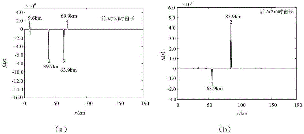
[0088] Example 1: with figure 1 The transmission line shown is taken as an example. The Q terminal of the line at this stage is in the form of multiple outgoing lines, and the new line is improved. k1 =30km, l k2 = 200km. The current-level line and the lower-level line are connected in the form of "one in and two out". Now suppose l MN A phase-to-earth fault occurred at a distance of 64km from the M terminal.

[0089] According to step 1 in the manual, the traveling wave data with the time window length of 3l′ / v is obtained through the measurement terminal; according to step 2, the current traveling wave and wave impedance of adjacent sound lines are used to construct the voltage traveling wave u M =i k ×Z c ; Calculate the distribution of voltage and current traveling waves along the line according to step 3 u x,s (x,t) and i x,s (x,t); Calculate the forward traveling wave and the reverse traveling wave u according to step 4 + x,s and u - x,s ; Calculate and extrac...

Embodiment 2

[0090] Example 2: with figure 1 The transmission line shown is taken as an example. The Q terminal of the line at this stage is in the form of multiple outgoing lines, and the new line is improved. k1 =30km, l k2 = 200km. The current-level line and the lower-level line are connected in the form of "one in and two out". Now suppose l MN A phase-to-earth fault occurred at a distance of 86km from the M terminal.

[0091] According to step 1 in the manual, the traveling wave data of 3l′ / v time window length is obtained through the measuring terminal; according to step 2, the current traveling wave and wave impedance of adjacent sound lines are used to construct the voltage traveling wave u M =i k ×Z c ; Calculate the distribution of voltage and current traveling waves along the line according to step 3 u x,s (x,t) and i x,s (x,t); Calculate the forward traveling wave and the reverse traveling wave u according to step 4 + x,s and u - x,s ; Calculate and extract the sudde...

Embodiment 3

[0092] Example 3: with figure 1 The transmission line shown is taken as an example. The Q terminal of the line at this stage is in the form of multiple outgoing lines, and the new line is improved. k1 =30km, l k2 = 200km. The current-level line and the lower-level line are connected in the form of "one in and two out". Now suppose l MN A phase-to-earth fault occurred at a distance of 94km from the M terminal.

[0093] According to step 1 in the manual, the traveling wave data of 3l / v time window length is obtained through the measurement terminal; according to step 2, the current traveling wave and wave impedance of adjacent sound lines are used to construct the voltage traveling wave u M =i k ×Z c ; Calculate the distribution of voltage and current traveling waves along the line according to step 3 u x,s (x,t) and i x,s (x,t); Calculate the forward traveling wave and the reverse traveling wave u according to step 4 + x,s and u - x,s ; Calculate and extract the sudd...


PUM


Abstract

The invention provides a chain type power transmission line single terminal fault location limited continuation method based on a characteristic of fault traveling wave distribution along line, belonging to the power system fault location technology field. The chain type power transmission line single terminal fault location limited continuation method comprises steps of obtaining current traveling wave data of a measurement-detection terminal which is obtained by a superior circuit measurement- detection terminal high speed collection device, utilizing current traveling waves of adjacent sound circuits and wave resistance to construct voltage traveling wave, utilizing the constructed voltage traveling wave and the current traveling wave to calculate the along-the-line voltage and current through a Bergeron circuit transmission equation, calculating forward traveling wave and backward traveling wave according to a direction traveling formula and calculating the location function along the longest circuit in the analysis time window of two following traveling waves, and obtaining a fault distance according to the mutational sites of the location function which are distributed along the line. The theory analysis and the simulation result express that the effect of the method is good.

Description

technical field [0001] The invention relates to a limited extension method for single-ended fault location of a chain transmission line based on the distribution characteristics of fault traveling waves along the line, and belongs to the technical field of power system fault location. Background technique [0002] The task of fault location is to calculate the fault distance through the measured current, voltage and line impedance at both ends of the line when a fault occurs at a certain point of the line. Generally, there are two main types of fault location methods for transmission lines. One is the impedance method, which is an algorithm that directly calculates the fault impedance or its percentage; the other is the traveling wave method, which uses the traveling waves of high-frequency fault transient current and voltage. and so on to indirectly determine the distance of the fault point. [0003] Transmission line traveling wave fault location has experienced two stage...

Claims


Application Information

Patent Timeline
Patent Type & Authority Applications(China)
IPC IPC(8): G01R31/08
CPCG01R31/085G01R31/088
Inventor 束洪春田鑫萃
Owner KUNMING UNIV OF SCI & TECH
Why Eureka
Try Eureka