Integration Method and Structure of Transformer and Inductor

A technology for transformers and transformer windings, applied in the field of transformers, can solve problems such as affecting efficiency, magnetic loss of common magnetic cores, and inconvenience for producers

Active Publication Date: 2019-03-01
SUPER FLOWER COMP +1
View PDF9 Cites 0 Cited by
  • Summary
  • Abstract
  • Description
  • Claims
  • Application Information

AI Technical Summary

Problems solved by technology

[0004] Although the above-mentioned Chinese invention patent CN 101308724A proposes a technical solution that can reduce the overall volume of the magnetic element and increase the power density of the power electronic converter, the "Tian"-shaped closed magnetic core in the space position It is a fixed structure. When faced with the magnetic integration structure that needs to produce transformers and inductors with different inductances, this structure needs to re-produce "Tian"-shaped magnetic cores of different sizes to solve it. Therefore, for production In addition, it is inconvenient to adjust the inductance of the inductance winding of the integrated structure quickly, and it lacks the flexibility to adjust the electrical characteristics. In addition, the magnetic flux generated by the transformer winding and the inductance winding is on the common magnetic core of the two. In the opposite direction, although part of it can be offset, there is still magnetic loss on the common core, which affects its efficiency

Method used


Image

  • Integration Method and Structure of Transformer and Inductor
  • Integration Method and Structure of Transformer and Inductor
  • Integration Method and Structure of Transformer and Inductor

Examples


Embodiment Construction

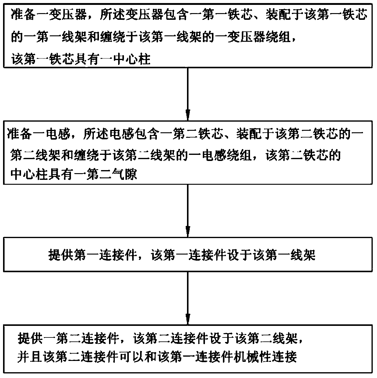
[0052] See first Figure 1 to Figure 4 It is a flow chart of the steps of an embodiment of the method for integrating transformers and inductors of the present invention. An embodiment of the method for integrating transformers and inductors proposed by the present invention includes:

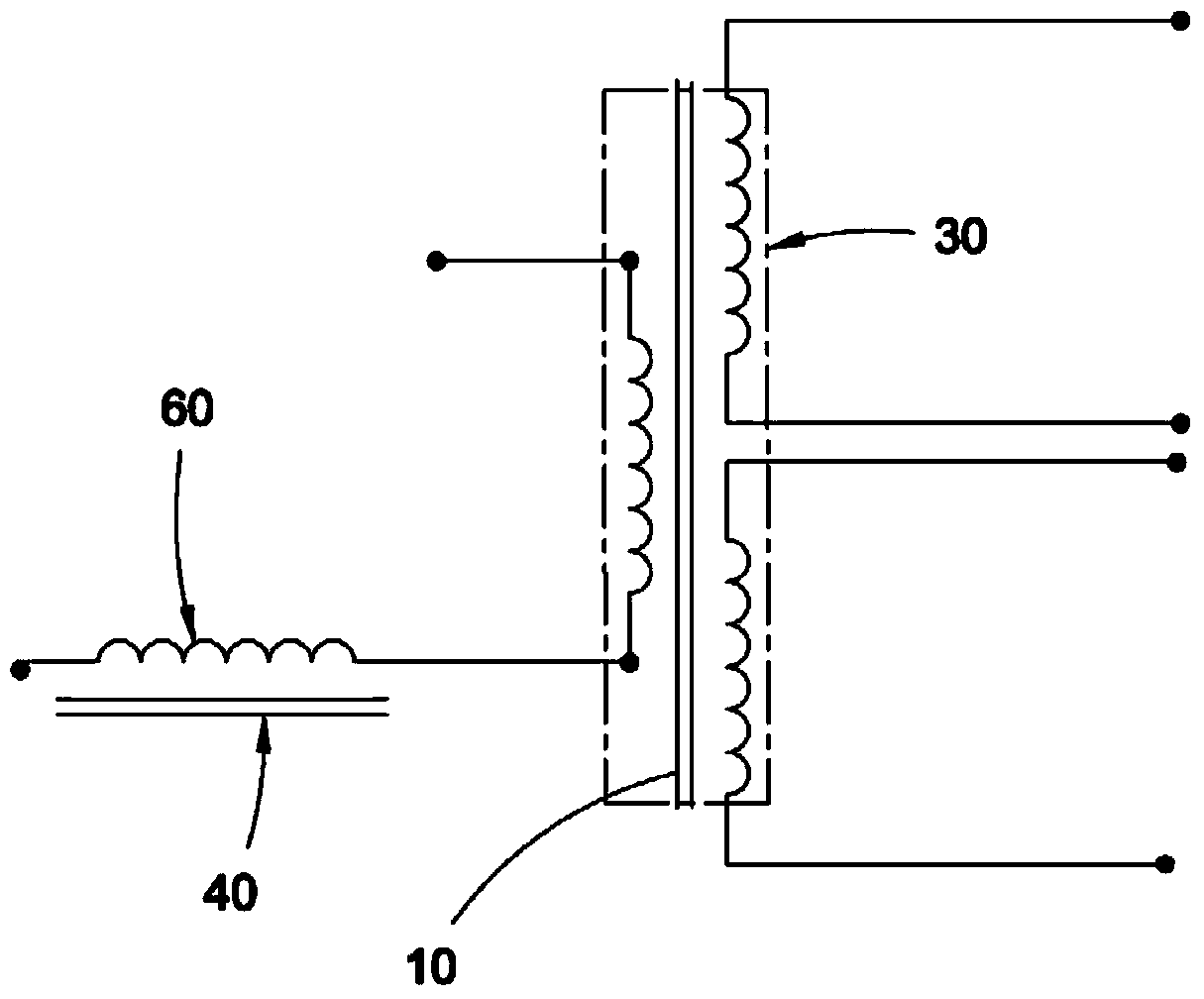
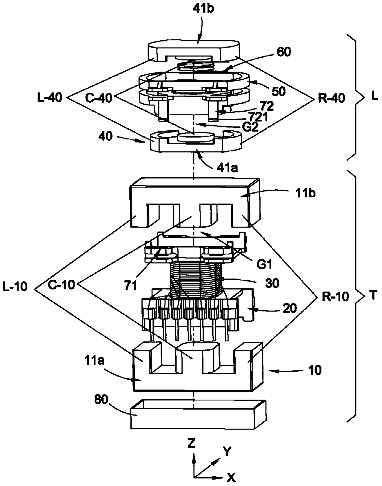
[0053] Prepare a transformer T, the transformer T includes a first iron core 10 (see image 3 structure of an embodiment), a first bobbin 20 assembled on the first iron core 10 and a transformer winding 30 wound on the first bobbin 20, the center column C-10 of the first iron core has a first an air gap G1, or alternatively the central column C-10 of the first core is designed without incorporating an air gap;

[0054] Prepare an inductance L, the inductance L comprises a second iron core 40, a second wire frame 50 assembled on the second iron core 40 and an inductance winding 60 wound on the second wire frame 50, the central column of the second iron core C-40 has a second air gap G2;

[00...


PUM


Abstract

The invention provides a combining method and a combining structure of a transformer and an inductor. The combining structure comprises a first iron core, a first coil holder assembled on the first iron core, a second iron core, and a second coil holder assembled on the second iron core. The first iron core comprises two first open iron cores. The second iron core comprises two second open iron cores. A first transformer winding is wound around the first coil holder, and an inductor winding is wound around the second coil holder. A central column of the first iron core has a first air gap or is designed to have no combination air gap. A central column of the second iron core has a second air gap. The first coil holder is provided with a first connecting member. The second coil holder is provided with a second connecting member, which can be mechanically connected to the first connecting member. The advantages are that the inductor and the transformer can be conveniently combined to form a whole body by means of the first connecting member and the second connecting member, inductors and transformers different in inductance or dimension can be flexibly selected and combined, inductors different in inductance can be easily combined and modulated, and the combining structure is convenient to produce.

Description

technical field [0001] The invention relates to a transformer, in particular to an integration method and structure of a transformer and an inductor. Background technique [0002] For power / electronic transformers, how to reduce the size of the transformer and improve the efficiency of the transformer (such as improving the power factor (power factor, PF) and reducing energy loss is one of the concerns of transformer designers. Traditional transformers are composed of Composed of iron core and coil (including at least the coil of primary winding and secondary winding), for many electronic equipment / devices today, in the face of the need for high power conversion efficiency and the ability to provide a variety of power supplies (such as a variety of Different voltage or current), the traditional transformer has been difficult to solve the above problems, so the power converter (such as: computer power supply or switching power supply) produced by combining the traditional tra...

Claims


Application Information

Patent Timeline
Patent Type & Authority Patents(China)
IPC IPC(8): H02M1/00H01F27/24H01F27/28
Inventor 蔡宗彦刘国泉
Owner SUPER FLOWER COMP
Why Eureka
Try Eureka