Housing, in particular outer housing for low-pressure steam turbine

A technology for steam turbines and outer casings, applied in mechanical equipment, engine components, engine manufacturing, etc., can solve problems such as high assembly costs and high costs, and achieve the effects of low-cost manufacturing and assembly, reduced complexity, and fast costs.

Inactive Publication Date: 2016-03-02
SIEMENS AG
View PDF8 Cites 1 Cited by
  • Summary
  • Abstract
  • Description
  • Claims
  • Application Information

AI Technical Summary

Problems solved by technology

However, the frame-like construction of the interior of the reinforcing bar has th

Method used


Image

  • Housing, in particular outer housing for low-pressure steam turbine
  • Housing, in particular outer housing for low-pressure steam turbine

Examples


Embodiment Construction

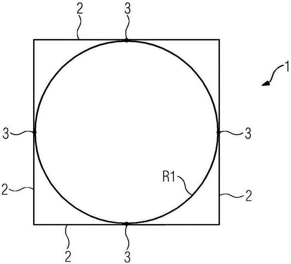
[0013] figure 1 A plan view of the lower part 1 of the housing of the welded condenser with the low-pressure steam turbine is shown. The large-area lateral panel walls 2 on the bottom of the rectangle—here a square—delimit the volume of the lower part and together with the upper part form the housing of the low-pressure steam turbine. The four side panel walls 2 are welded to each other and to the base plate at their respective edges. The panel wall 2 itself does not have sufficient inherent stiffness due to its large-area sheet metal construction. As a result, indentations can occur due to large pressure differences between the environment and the non-metallic volume, so that safe operation of the low-pressure steam turbine is no longer guaranteed.

[0014] According to the invention, therefore, an annular reinforcement element R1 is provided for the reinforcement of a large-area panel wall, which at the same time also has the simplest possible construction and low costs an...


PUM


Abstract

The invention relates to a housing, in particular an outer housing for a low-pressure steam turbine, which has, in its main surface, a substantially rectangular cross-section and in which the surfaces of lateral sheet metal walls (2) form parts of the housing. To reinforce the sheet metal walls (2), at least one annular reinforcing element (R1, R2, R3) is inserted and designed in such a way that it supports the sheet metal walls at points of the surfaces (3, 3').

Description

technical field [0001] The invention relates to a housing according to the preamble of claim 1 , in particular an outer housing for a low-pressure steam turbine. Background technique [0002] An example of a casing, in particular an outer casing for a low-pressure steam turbine, is known from EP0575642A1. Here, the outer housing is embodied as a welded structure and consists of an upper part and a supporting lower part. The lower part of the support connects the condenser underneath. Together they then form a closed space against an environment where atmospheric pressure prevails. Since there is a condenser pressure within the outer housing which generally moves in the double-digit millibar range, the entire ambient pressure acts on the outer housing. Since the outer housing is designed as a large-area sheet metal structure, the problem arises that relatively high forces act on the skin from the large-area sheet metal walls, and deformations likewise occur as a result. C...

Claims


Application Information

Patent Timeline
IPC IPC(8): F01D25/28
CPCF01D25/28F05D2250/12F05D2250/141
Inventor D·巴科维斯基M·艾特勒R·霍法克B·科克德米尔S·沃斯
Owner SIEMENS AG
Why Eureka
Try Eureka