Dust prevention structure for dental handpiece

A technology of dust-proof structure and dental handpiece, which is applied in dentistry, dental drilling, medical science, etc., can solve the problems of increasing the wear and tear of front bearing 501), wear, and unusable handpieces, so as to weaken the axial negative pressure return. Suction phenomenon, strengthen dustproof effect, prolong life effect

Active Publication Date: 2016-03-09
SINOL MEDICAL EQUIP GRP CO LTD
View PDF9 Cites 6 Cited by
  • Summary
  • Abstract
  • Description
  • Claims
  • Application Information

AI Technical Summary

Problems solved by technology

Its structure usually includes a handle and a machine head. The machine head includes a machine head shell 1 and a gland 7 that is adapted to connect with the machine head shell 1 through a bearing seat 8. A movement is arranged inside the machine head shell 1. The movement mainly includes a machine The core turbine 6 and the core shaft 4 driven by the core turbine 6 to rotate, wherein the two ends of the core shaft 4 are equipped with bearings 5, and the bearings 5 ​​include a front end bearing 501 and a rear end bearing 502, wherein the machine The front-end bearing 501 of the core shaft 4 is the most easily worn part in the mobile phone. Once the front-end bearing 501 is damaged, the mobile phone cannot be used. At this time, the tooth powder will enter the front bearing 501 of the mobile phone head, increasing the wear and tear of the front bearing 501) At the moment of the machine, the movement turbine 6 continues to rotate under the action of inertia, so that the center of the air chamber of the movement turbine 6 forms a momentary negative pressure, The instant negative pressure is very easy to directly suck the powdery tooth chips produced by the mobile phone grinding teeth into the installation position where the front end bearing 501 is located (such as Figure 5 As shown), it

Method used


Image

  • Dust prevention structure for dental handpiece
  • Dust prevention structure for dental handpiece
  • Dust prevention structure for dental handpiece

Examples


Embodiment Construction

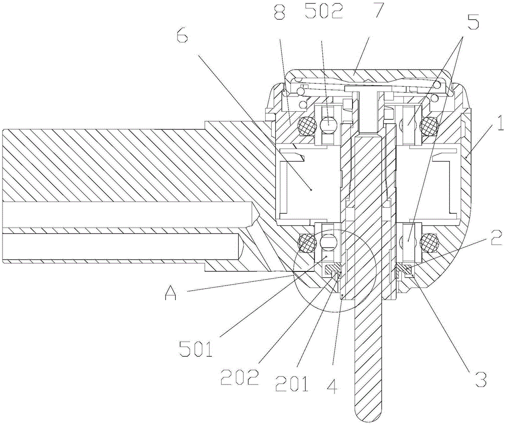
[0019] Attached below Figure 1-4 An embodiment of the present invention is described.

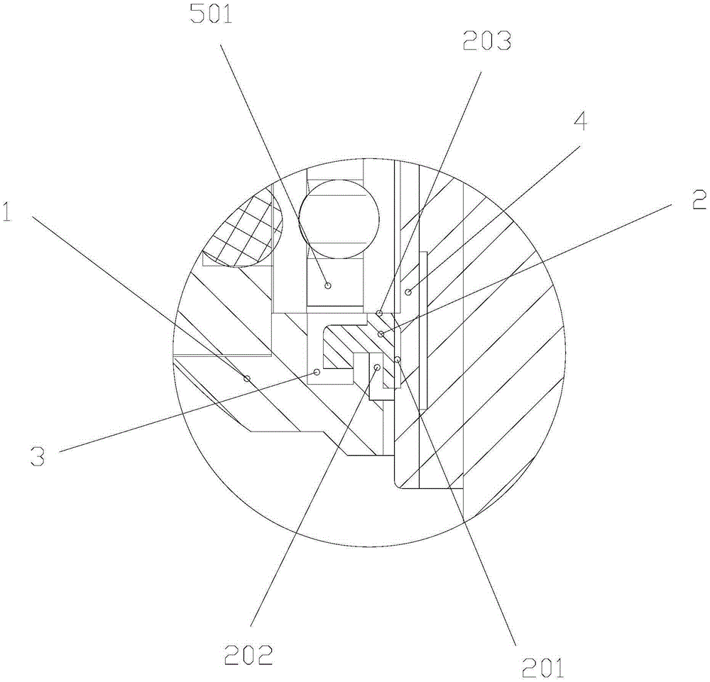
[0020] Dust-proof structure for dental handpieces (such as figure 1 As shown), the dental handpiece is composed of a handle and a machine head. The machine head has a machine head shell 1. The upper end of the machine head shell 1 is sealed and fixedly connected with the lower part of the bearing seat 8. The upper part of the bearing seat 8 is provided with a gland 7. The machine head shell 1. There is a movement inside. The movement mainly includes a movement turbine 6 and a movement shaft 4 driven by the movement turbine 6. The front end of the movement shaft 4 is supported in the nose shell 1 through a front bearing 501. The rear end of the main shaft 4 of the movement is supported in the bearing housing 8 through the rear end bearing 502. The front end bearing 501 is the most easily worn part in the mobile phone. In order to avoid wear and tear, a groove I3 is formed in the head shel...


PUM


Abstract

The invention provides a dust prevention structure for a dental handpiece. The dust prevention structure comprises a handpiece shell. A handpiece core is arranged in the handpiece shell and mainly comprises a handpiece core turbine and a handpiece-core large shaft driven by the handpiece core turbine to rotate. The handpiece-core large shaft is supported into the handpiece shell through a bearing piece, and the bearing piece comprises a front end bearing and a back end bearing; a first groove is formed in the handpiece shell and formed below the front end bearing, a dust prevention cover is arranged in the first groove and is a hollow columnar piece, and the hollow inner wall of the dust prevention cover is in close fit with the outer wall of the handpiece-core large shaft; a second groove which is provided with a downward opening and is used for changing a sucking path is formed in the outer portion of the dust prevention cover. The dust prevention structure is simple in structure and easy to achieve, and the pollution problem and the wear problem of the front end bearing are solved through the dust prevention cover and the first groove; compared with the prior art, the dust prevention structure has more stable and durable characteristics, and the service life of the handpiece is objectively prolonged.

Description

technical field [0001] The invention belongs to the technical field of dental medical instruments, and in particular relates to a dustproof structure for a dental handpiece. Background technique [0002] The dental handpiece is a commonly used medical device in the department of stomatology. Its working principle is to use the air compressor to compress the air into high-pressure gas to blow the turbine to drive the bur to run at a high speed. The speed is usually about 360,000 revolutions per minute. Cutting teeth to remove bad tissue, or preparing porcelain teeth, can also be used for oral treatment such as grinding dentures. Its structure usually includes a handle and a machine head. The machine head includes a machine head shell 1 and a gland 7 that is adapted to connect with the machine head shell 1 through a bearing seat 8. A movement is arranged inside the machine head shell 1. The movement mainly includes a machine The core turbine 6 and the core shaft 4 driven by t...

Claims


Application Information

Patent Timeline
IPC IPC(8): A61C1/16
CPCA61C1/16
Inventor 解辽波孙建龙郭忙强
Owner SINOL MEDICAL EQUIP GRP CO LTD
Why Eureka
Try Eureka