
Bubble tower and method for wet flue gas desulphurization

A technology of wet flue gas desulfurization and bubble tower, which is applied in the field of flue gas desulfurization, can solve problems such as easy fouling of the bubble tube and blockage of the normal operation of the bubble tower, so as to increase the gas-liquid contact area, improve the desulfurization efficiency, and reduce the Effect of perforation air velocity

Active Publication Date: 2016-03-09
ZHEJIANG TIANLAN ENVIRONMENTAL PROTECTION TECH
View PDF6 Cites 10 Cited by
  • Summary
  • Abstract
  • Description
  • Claims
  • Application Information

AI Technical Summary

Problems solved by technology

[0005] In view of the above problems, the present invention provides a bubble tower and method for wet flue gas desulfurization, which mainly solves the technical problem that the bubble tubes of the existing bubble tower are easy to be fouled and blocked, which affects the normal operation of the bubble tower

Method used


Image

  • Bubble tower and method for wet flue gas desulphurization
  • Bubble tower and method for wet flue gas desulphurization
  • Bubble tower and method for wet flue gas desulphurization

Examples


Embodiment 1

[0076] The flue gas desulfurization project of two 75T heating boilers in a printing and dyeing factory adopts this process, and the SO in the flue gas 2 The concentration is 2316mg / Nm 3 , the dust concentration is 85mg / Nm 3, the flue gas temperature is 142°C; the humidification spray liquid-gas ratio is 2.8L / Nm 3 , the diameter of the bubble hole is 25mm, the diameter of the rectifier plate is 30mm, the opening rate is 30%, and the liquid-gas ratio of the flushing water pipe is 1.5L / Nm 3 ; The diameter of the slurry hole is 15mm; the desulfurization efficiency is 98.9%, and the dust content at the outlet is 3.7mg / Nm 3 .

Embodiment 2

[0078] A thermal power plant, a 130T boiler flue gas desulfurization project adopts this process, SO in the flue gas 2 The concentration is 3060mg / Nm3, the dust concentration is 122mg / Nm3, the flue gas temperature is 118°C; the humidification spray liquid-gas ratio is 2.4L / Nm 3 , the diameter of the bubble hole is 30mm, the diameter of the rectifier plate is 30mm, the opening rate is 33%, and the liquid-gas ratio of the flushing water pipe is 1.2L / Nm 3 ; The diameter of the slurry hole is 18mm; the desulfurization efficiency is 99.2%, and the dust content at the outlet is 4.1mg / Nm 3 .


PUM

PropertyMeasurementUnit
pore sizeaaaaaaaaaa
pore sizeaaaaaaaaaa
heightaaaaaaaaaa

Abstract

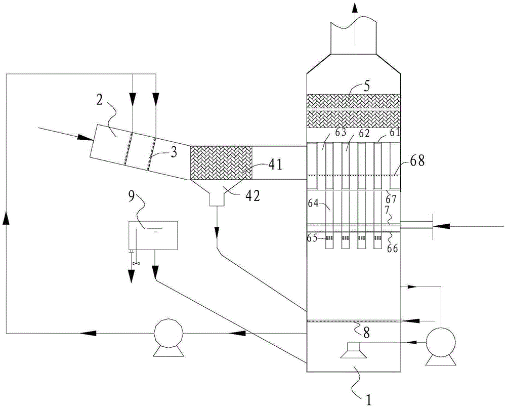
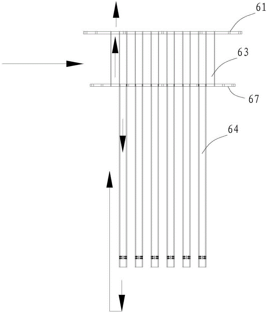
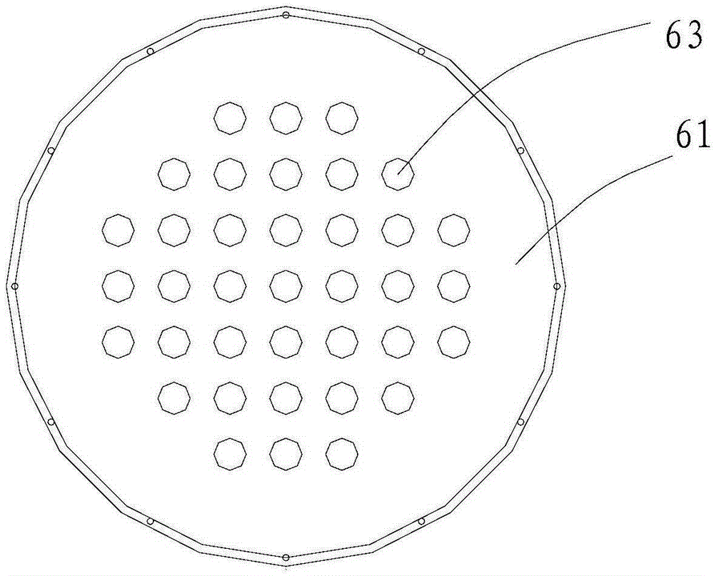
The invention discloses a bubble tower and method for wet flue gas desulphurization. The bubble tower comprises an absorbing tower, a bubbling mechanism is arranged in the absorbing tower, the bubbling mechanism is connected to an inlet flue, a humidifying spray mechanism and a dust pre-removal mechanism are orderly arranged in the inlet flue along a flue gas flow direction, the bubbling mechanism comprises a sealed flue gas inlet zone formed from an upper separation plate, a lower separation plate and inner walls of the absorbing tower, the sealed flue gas inlet zone is communicated with the inlet flue, the bubble tower also comprises several vertical bubbling pipes, the upper ends of the bubbling pipes go through the lower separation plate and are communicated with the flue gas inlet zone, the lower ends of the bubbling pipes stretch into the tower bottom, the bubble tower also comprises several vertical flue gas discharge pipes, the flue gas discharge pipes go through the upper separation plate and the lower separation plate, the flue gas discharge pipes and the bubbling pipes are staggered, the bubble tower comprises a flushing pipe network, the flushing pipe network is arranged in the flue gas inlet zone and is located above inlets of the bubbling pipes, and the flushing pipe network is provided with several atomizing nozzles. The bubble tower and method are used for wet flue gas desulphurization and mainly solve the problem that the existing bubble tower easily produces scale in the bubbling pipes so that the bubbling pipes are blocked and bubbling tower normal operation is influenced.

Description

technical field [0001] The invention relates to the technical field of flue gas desulfurization, in particular to a device and method for wet flue gas desulfurization using a bubble tower. Background technique [0002] Flue gas desulfurization technology can be divided into three types: wet method, dry method and semi-dry method. Among them, wet method desulfurization technology has become the main method of flue gas desulfurization. At present, the desulfurization towers commonly used in coal-fired power plants at home and abroad mainly include spray hole towers and packed towers. [0003] Beijing Boqi Electric Power Technology Co., Ltd. has applied for a number of patents to study the wet desulfurization technology of the bubble tower. Among them, the Chinese utility model patent with the application number 200720309256.6 discloses a flue gas desulfurization system. The desulfurization tower adopts a bubble tower, and the device is modified at the flue gas cooler. There i...

Claims


Application Information

Patent Timeline
Patent Type & Authority Applications(China)
IPC IPC(8): B01D53/80B01D53/50B01D50/00
CPCB01D50/00B01D53/502B01D53/504B01D2251/404B01D2257/302
Inventor 莫建松王岳军李泽清陈美秀吴忠标
Owner ZHEJIANG TIANLAN ENVIRONMENTAL PROTECTION TECH
Learn More