Device and method for welding target through stirring friction

A friction stir and target material technology, which is applied in welding equipment, welding/welding/cutting items, non-electric welding equipment, etc., can solve the problems of large difference in thermal expansion coefficient between ceramics and metals, affecting welding quality, material deformation, etc., to achieve enhanced Stir friction effect, easy operation, low heat effect

Active Publication Date: 2016-03-09
FUJIAN ACETRON NEW MATERIALS CO LTD
View PDF8 Cites 3 Cited by
  • Summary
  • Abstract
  • Description
  • Claims
  • Application Information

AI Technical Summary

Problems solved by technology

[0002] In the Chinese patent document (CN102916137A), a packaging mechanism for an organic electroluminescent device is disclosed, and the following technical scheme is disclosed in detail: it includes a substrate, a cover plate, and a sealing layer, and also includes a device for heating the sealing layer. Built-in resistance heating layer, and place a heavy object on the cover plate, so that the pressure of the sealing layer of the cover plate and the sealing layer of the substrate is 1-2KG / cm 2 , the sealing layer is indium; the heating device uses a resistance heating mode to generate heat to melt the indium coating. The disadvantage of this solution is that it is only suitable for the welding of low-melting-point metals between ceramic targets and metal substrates with small areas. When it is applied to the welding of large-area ceramic targets and metal substrates with low melting point metals, due to the large difference in thermal expansion coefficient between ceramics and metals, if the welding area is too large, the indium binding will be uneven, resulting in indium melting and outflow affecting welding. mass, will cause deformation and cracking of the material

Method used


Image

  • Device and method for welding target through stirring friction
  • Device and method for welding target through stirring friction

Examples


Embodiment Construction

[0027] The present invention will be described in detail below in conjunction with the accompanying drawings and specific embodiments.

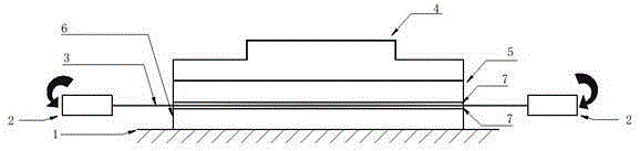
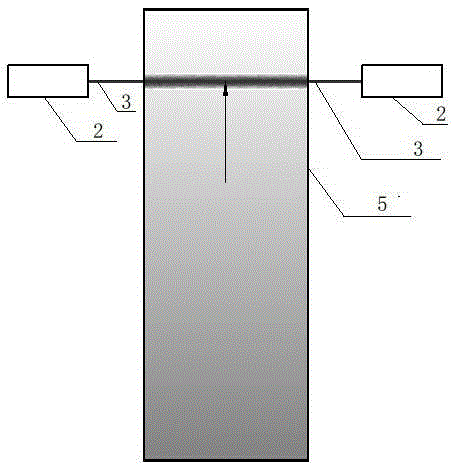
[0028] see Figure 1-2 , a method for friction stir welding target materials, comprising an indium binding device and a packaging structure, the indium binding device includes a horizontal platform 1, a controllable motor 2, a metal wire 3 and a fixed locking mechanism 4, the controllable There are two motors 2, which are horizontally and symmetrically distributed on both sides of the horizontal platform 1. Both ends of the metal wire 3 are fixedly connected to the rotating shaft of the controllable motor 2. The packaging structure includes a ceramic target 5, a metal substrate 6 and a ceramic Two welding layers 7 on the bonding surface of the target material 5 and the metal substrate 6, the welding layer 7 is metal indium or indium alloy coating, and the fixing and locking mechanism 4 fixes the packaging structure on the horizontal platform ...


PUM

PropertyMeasurementUnit
thicknessaaaaaaaaaa
tensile strengthaaaaaaaaaa
diameteraaaaaaaaaa

Abstract

The invention relates to a device and method for welding a target through stirring friction. The device comprises an indium binding device and an encapsulating structure. The method for welding the target through stirring friction comprises the sequential steps that firstly, binding surfaces of ceramic target and a metal substrate are each coated with a welding layer through a thermal coating method; secondly, the ceramic target coated with the welding layer and the metal substrate coated with the welding layer in the first step are horizontally placed on a horizontal table; thirdly, a metal wire rotating at a high speed is adjusted so that the metal wire can exactly face a seam of the two welding layers of the binding surfaces of the ceramic target and the metal substrate; fourthly, binding bonding welding work is started, the rotating speed of a controllable motor is adjusted, the moving speed of the horizontal table is adjusted, and the horizontal table is horizontally moved in the radial direction of the metal wire. By means of the method, the defect that when ceramic target and a metal substrate are welded through a traditional resistance heating method, deformation and cracking occur after welding due to the large difference of the coefficients of thermal expansion can be effectively overcome.

Description

technical field [0001] The invention relates to a device and a method for welding a target, in particular to a device and a method for friction stir welding a target. Background technique [0002] In the Chinese patent document (CN102916137A), a packaging mechanism for an organic electroluminescent device is disclosed, and the following technical scheme is disclosed in detail: it includes a substrate, a cover plate, and a sealing layer, and also includes a device for heating the sealing layer. Built-in resistance heating layer, and place a heavy object on the cover plate, so that the pressure of the sealing layer of the cover plate and the sealing layer of the substrate is 1-2KG / cm 2 , the sealing layer is indium; the heating device uses a resistance heating mode to generate heat to melt the indium coating. The disadvantage of this solution is that it is only suitable for the welding of low-melting-point metals between ceramic targets and metal substrates with small areas. ...

Claims


Application Information

Patent Timeline
Patent Type & Authority Applications(China)
IPC IPC(8): B23K20/12B23K20/24B23K103/18
CPCB23K20/1225B23K20/1245B23K2103/18
Inventor 陈钦忠张科邱树将
Owner FUJIAN ACETRON NEW MATERIALS CO LTD
Why Eureka
Try Eureka