
Thermal stress crack initiation method of surface annular groove root of bar blanking

A technology of annular groove and thermal stress, which is applied in the direction of heat treatment furnace, heat treatment equipment, process efficiency improvement, etc., can solve the problems of increasing turning flat section process, reducing production efficiency, increasing production cost, etc., so as to shorten the blanking time and improve The effect of blanking efficiency

Active Publication Date: 2016-03-09
XI AN JIAOTONG UNIV
View PDF5 Cites 3 Cited by
  • Summary
  • Abstract
  • Description
  • Claims
  • Application Information

AI Technical Summary

Problems solved by technology

The shearing blanking method is widely used in industrial production, but the section of the bar stock produced by ordinary shearing blanking is obviously horseshoe-shaped, and the quality of the section is poor. It is necessary to increase the process of turning and flattening the section, which reduces the production efficiency and increases the production cost. waste material
[0003] In recent years, the low-stress bar precision blanking technology developed by using the prefabricated notch stress concentration effect and dynamic crack propagation method has made new breakthroughs in the metal bar blanking process. The circumferential direction proposed by Chinese patents 201320338632. Low-stress bending fatigue fracture precision blanking machines have achieved chip-free and material-saving production, but due to the long life of dynamic crack growth, the blanking efficiency still cannot meet mass production

Method used


Image

  • Thermal stress crack initiation method of surface annular groove root of bar blanking
  • Thermal stress crack initiation method of surface annular groove root of bar blanking
  • Thermal stress crack initiation method of surface annular groove root of bar blanking

Examples


Embodiment Construction

[0021] The present invention will be described in detail below in conjunction with the accompanying drawings.

[0022] A method for initiating thermal stress cracking at the root of an annular groove on the surface of a bar blanking, comprising the following steps:

[0023] Step 1, according to the required blanking length, use a slotting machine to process equidistant annular grooves 22 on the surface of the metal bar 1, such as figure 1 shown;

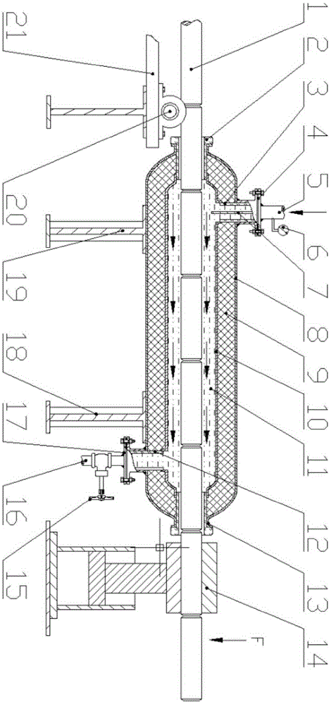
[0024] Step 2, refer to figure 2 , close the gate valve 15, quickly fill the cryogenic device with liquid nitrogen 11 through the liquid inlet pipe 5, and keep the temperature in the cryogenic device between -130°C and -196°C;

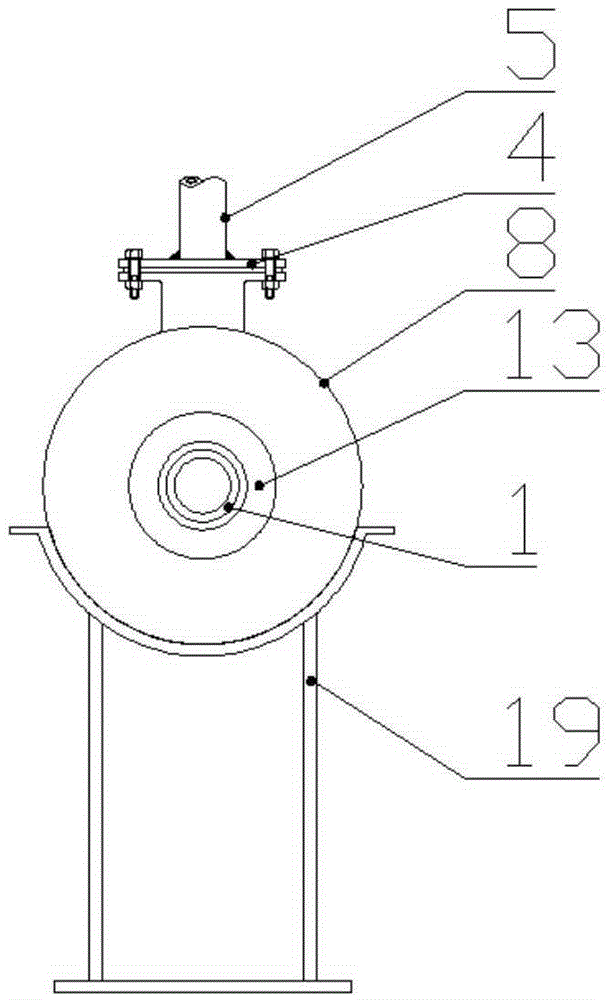
[0025] Step three, refer to figure 2 and image 3 Place the metal bar 1 on the feeding frame 21, and send it into the cryogenic device through the rollers 20 provided on the feeding frame 21 to carry out subsection rapid cryogenic cooling. At the moment of cooling, the surface of the metal bar 1 is rapi...


PUM


Abstract

The invention discloses a thermal stress crack initiation method of a surface annular groove root of bar blanking. Before crack initiation, an annular groove is prefabricated in the surface of a metal bar, a deep cooling device is rapidly charged with liquid nitrogen, and the temperature in the deep cooling device is kept between -196 DEG C and -130 DEG C. Then, the metal bar is fed into the deep cooling device to be subjected to segmented rapid deep cooling. At the moment the cooling starts, due to the fact that the surface temperature is lower than the core temperature, the surface of the metal bar is sharply cooled and shrunk, large stress concentration is generated at the bottom of the annular groove under the instant tensile stress and the notch effect, and a microcrack cluster is produced. After crack initiation is ended, the metal bar is fed into a blanking machine to be subjected to segmented blanking. The notch effect and the thermal stress function are utilized, dynamic cracks generated in the later blanking process can enter the expanding stage more rapidly, and the overall blanking efficiency is improved.

Description

technical field [0001] The invention belongs to the technical field of precision blanking of metal rods, and in particular relates to a method for initiating thermal stress cracking at the root of an annular groove on the surface of blanked rods. Background technique [0002] Metal bar blanking widely exists in various shafts, metal standard parts, internal combustion engine accessories (such as piston pins, tappets), cold extrusion, precision die forging and other material preparation processes, and its cutting efficiency and section quality will directly affect Manufacturing accuracy, production efficiency and economic cost of parts. The traditional blanking process mainly adopts lathe cutting and sawing machine sawing methods. The section of the blank bar is flat, but the blanking efficiency is too low. The shearing blanking method is widely used in industrial production, but the section of the bar stock produced by ordinary shearing blanking presents an obvious horsesho...

Claims


Application Information

Patent Timeline
IPC IPC(8): C21D6/04C21D9/00
CPCC21D6/04C21D9/0075Y02P10/20
Inventor 赵升吨董渊哲任芋见曹苗钟玮
Owner XI AN JIAOTONG UNIV
Learn More