Advanced roller flow control valve and application

A flow regulation, advanced technology, applied in the direction of flow control, control/regulation system, non-electric variable control, etc., can solve the problems of unable to achieve quantitative regulation, flow change, out of control, etc., achieve simple structure, improve reliability, Create convenient effects

Inactive Publication Date: 2016-03-09
钱建民
View PDF8 Cites 8 Cited by
  • Summary
  • Abstract
  • Description
  • Claims
  • Application Information

AI Technical Summary

Problems solved by technology

[0003] The purpose of the present invention is to solve the problem that the existing advanced roller flow adjustment switch cannot realize quantitative adjustment and is easy to move after the adjustment is in place, resulting in flow changes or even out of control. Advanced Roller Flow Adjustment Switch That Does Not Slip

Method used


Image

  • Advanced roller flow control valve and application
  • Advanced roller flow control valve and application
  • Advanced roller flow control valve and application

Examples


Embodiment 1

[0029] Such as Figure 1-3 shown.

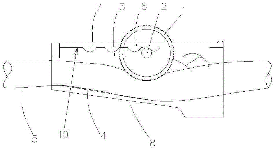
[0030] An advanced roller flow adjustment switch, which includes a roller 1 and a roller groove 3, which constrains the conduit 5 through which the fluid passes to perform advanced flow control and each stage of limit locking; the roller groove 3 contains advanced The step limit structure 7 is used to adjust the roller to enter each step and fix it in its position, so as to realize the functions of flow regulation and fixed lock; the advanced limit mechanism 7 contains one or more limit structures of different shapes , to achieve different flow control functions and fixed at each stage to keep the flow stable. See attached figure 1 The roller 1 of the advanced roller flow regulating switch of the present invention is fixedly installed on the roller shaft 2, at least one end of the roller shaft 2 protrudes from the end surface of the roller to prevent the roller 1 from breaking away from its roller groove 3, and the roller shaft protrudes f...

Embodiment 2

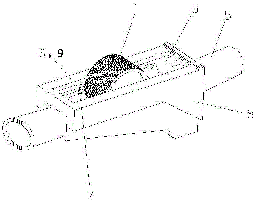
[0032] Such as Figure 4-6 shown.

[0033] As a case of a typical application of the present invention, such as Figure 4 A flushing catheter is shown, which includes a hand-held part 11, a flushing catheter 12 and a negative pressure suction catheter 13. The hand-held part 11 is equipped with a first step roller flow adjustment device for controlling the flow of the flushing catheter 12. The switch 14 and the second progressive roller flow regulating switch 15 for controlling the suction force of the negative pressure suction catheter 13 . The roller groove 3 for installing the roller 1 in the first progressive roller flow regulating switch 14 and the second progressive roller flow regulating switch 15 is directly formed on the handle 11 body. In specific implementation, the switch of the first embodiment can also be directly installed on the handle 11 of the embodiment.

Embodiment 3

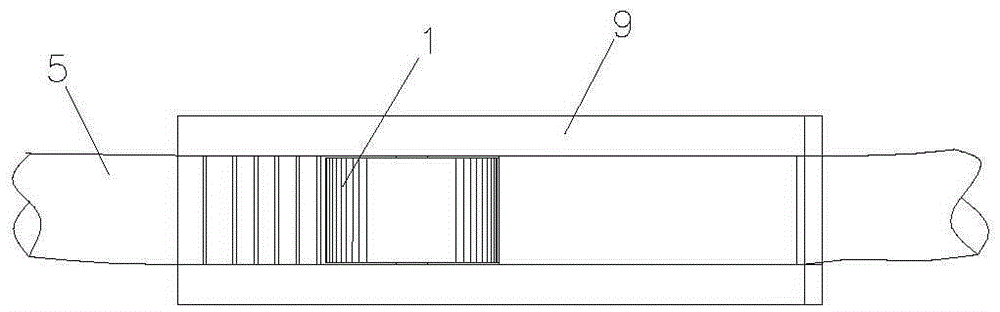
[0035] Such as image 3 shown.

[0036] An advanced roller flow regulating switch for infusion, which includes an installation housing 8, an infusion tube 5 passes through the installation housing 8, a roller 1 is installed on a roller shaft, and both ends of the roller shaft protrude from the end surface of the roller 1, The roller shaft 2 is constrained in the roller groove 3 by the elongated constraining structure 6 on the upper part of the installation housing, and a plurality of advanced limit structures 7 are arranged on the lower surface of the constraining structure 6 . When in use, the roller shaft 2 is driven by the rolling roller 1 to move along the constraint structure 6. During the movement, it is constrained by the inclined surface structure 4, the conduit 5 is squeezed, and the channel becomes smaller. When it moves to the desired position, the roller 1 is released. The roller shaft will automatically stop between the two adjacent advanced limit structures 7, a...


PUM


Abstract

The invention relates to an advanced roller flow control valve and application. The advanced roller flow control valve is characterized by comprising a roller (1) and a roller slot (3), wherein a catheter (5) through which fluid passes is restricted between the roller and the roller slot so as to be used for performing advanced flow control and limiting lock of each step; an advanced limiting structure (7) is arranged in the roller slot (3) so as to be used for regulating the roller to enter each step and fixed at the position; therefore, the functions of flow control and fixation locking are realized. The advanced roller flow control valve disclosed by the invention can be widely applied to various medical apparatus so that the steady flow control is realized. The advanced roller flow control valve has the advantages of being simple in structure and safe and reliable.

Description

technical field [0001] The invention relates to a flow regulating switch, in particular to a roller-type regulating switch capable of realizing step-by-step regulation of extruded air pipes or liquid conduits, in particular to a step-wise roller flow regulating switch and its application in medical equipment Applications. Background technique [0002] At present, there are many ways to regulate gas flow and liquid flow, some use complex mechanisms for precise flow regulation, and some use valves for regulation. In the field of medical equipment, especially in the operation process, it is often necessary to adjust the irrigation flow and negative pressure suction flow. For example, many surgical instruments such as irrigation catheters and electric coagulation knife need to adjust the flow. At present, it is commonly used to rely on auxiliary personnel. It is very inconvenient to operate by manual control or manual pressing. Generally speaking, the accuracy of this kind of ...

Claims


Application Information

Patent Timeline
Patent Type & Authority Applications(China)
IPC IPC(8): F16K7/06A61M5/168A61M3/02A61M1/00
CPCA61M39/28F16K7/068A61M1/00A61M3/02A61M5/16813
Inventor 钱建民孙芸
Owner 钱建民
Why Eureka
Try Eureka