
A mold heating device based on permanent magnetic induction

A technology of mold heating and magnetic induction, applied in the direction of electromechanical devices, magnetic circuit static parts, magnetic circuit shape/style/structure, etc., can solve the problems of mold overheating, high cost, low efficiency, etc., to avoid electrical loss and improve heating Quality and heating efficiency, energy saving effect

Inactive Publication Date: 2018-01-09
SHENZHEN YINHE INVESTMENT DEV
View PDF4 Cites 0 Cited by
  • Summary
  • Abstract
  • Description
  • Claims
  • Application Information

AI Technical Summary

Problems solved by technology

[0002] In the field of metal thermal processing, the supporting dies of extruders or forging presses need to be preheated before use. The advanced mold processing technology is to directly apply the high-frequency magnetic field generated by the charged coil to the heated mold, which bears a large induced current on a limited thickness, and the heating energy per unit area of ​​this large induced current is too large. Cause local overheating at the edges, sides, and corners of the mold, and damage the mold. In addition, the current flowing through the coil will cause electrical loss due to the resistance of the coil, which is not only inefficient, but also wastes energy, especially for larger coils. In other words, it is also necessary to use treated cooling water to lower the temperature, resulting in a complex structure and high cost of the heating device

Method used


Image

  • A mold heating device based on permanent magnetic induction
  • A mold heating device based on permanent magnetic induction
  • A mold heating device based on permanent magnetic induction

Examples


Embodiment Construction

[0025] The present invention will be described in more detail below in conjunction with the accompanying drawings and embodiments.

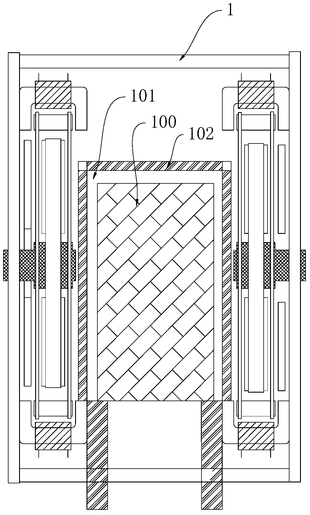
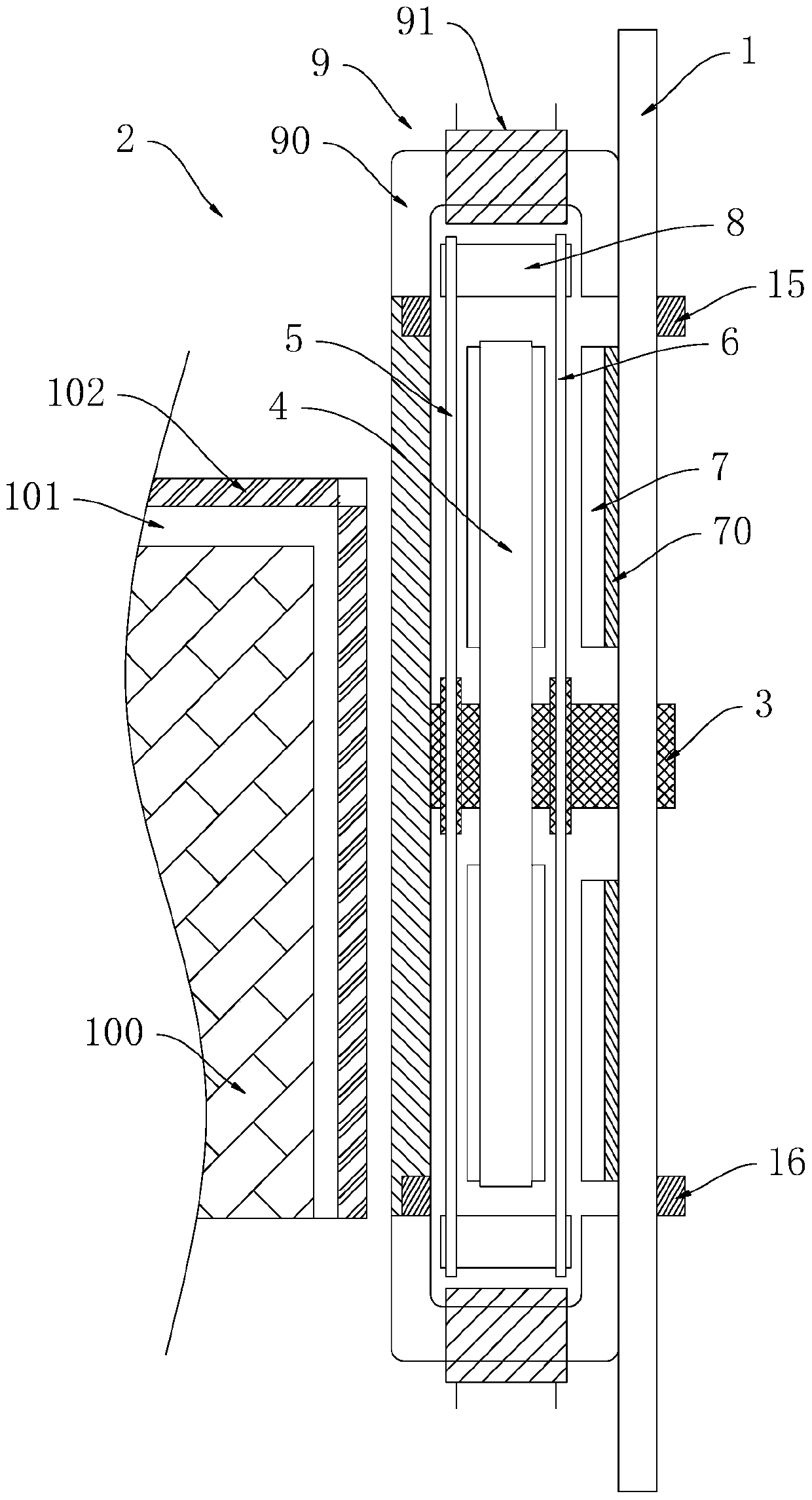
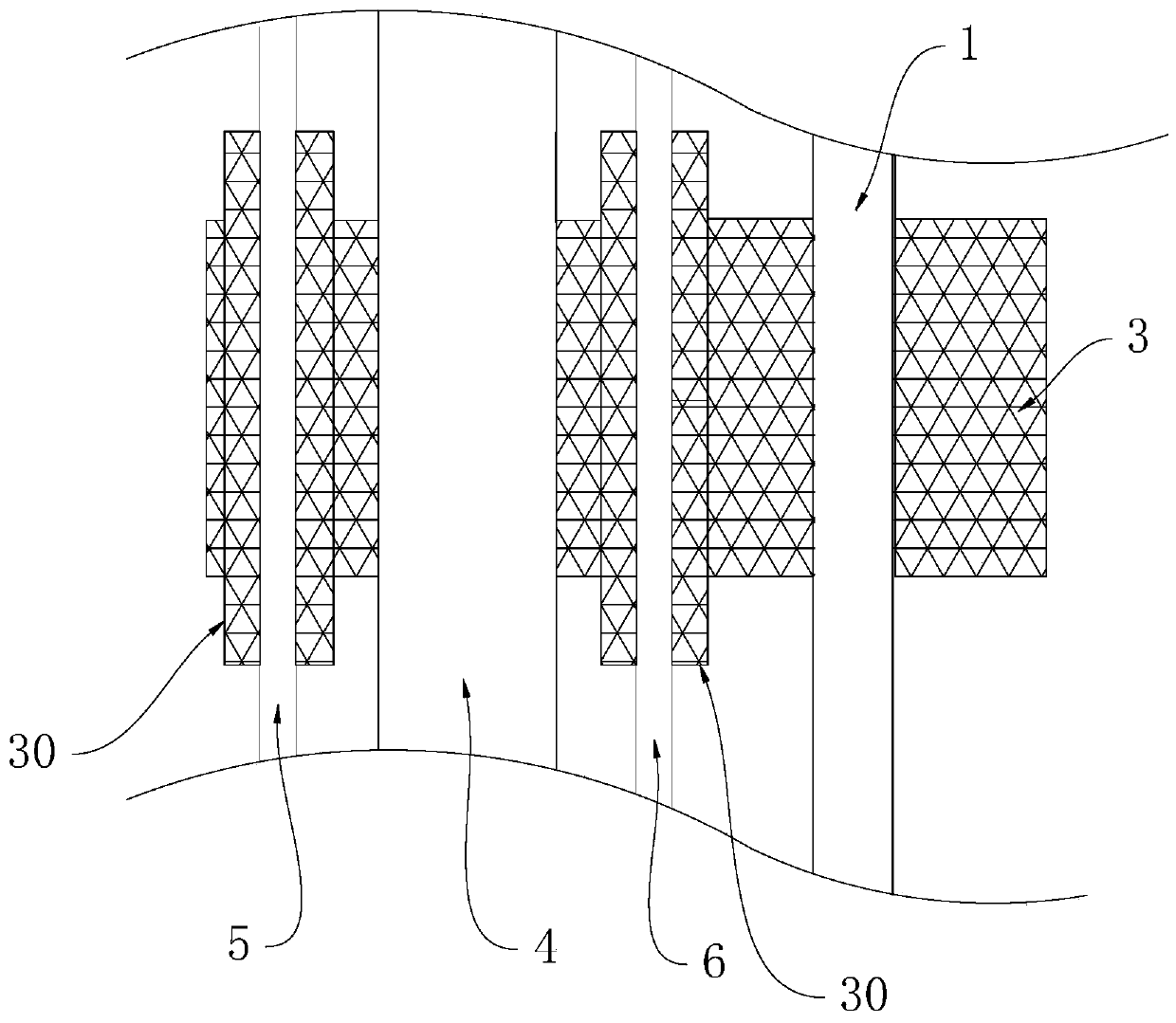
[0026] The invention discloses a mold heating device based on permanent magnet induction, which combines Figure 1 to Figure 9 As shown, it includes a frame 1, the frame 1 is provided with a bearing position 101 for placing the mold 100, the frame 1 is provided with a stator assembly and a rotor assembly 2, and a permanent mold is formed on the stator assembly. Magnetic field, the rotor assembly 2 is used to convert the permanent magnetic field into an alternating magnetic field to act on the mold 100 when it rotates.

[0027] In the above-mentioned mold heating device based on permanent magnetic induction, under the condition of continuous rotation of the rotor assembly, the converted alternating magnetic field acts on the mold on the bearing position, so that eddy currents are generated on the mold, and the mold is heated by the eddy current. T...


PUM


Abstract

The invention discloses a permanent magnet induction-based die heating device, which comprises a rack, wherein a bearing position for placing a die is arranged on the rack; the rack is provided with a stator assembly and a rotor assembly; a permanent magnetic field is formed on the stator assembly; and the rotor assembly is used for converting the permanent magnetic field into an alternating magnetic field to act on the die when rotating. The die heating device generates the alternating magnetic field when the rotor assembly rotates; and the alternating magnetic field is in a low-frequency state due to the limitation of the rotating speed of the rotor assembly. Compared with the prior art, damages to edges, sides and corners of the die caused by a high-frequency magnetic field are avoided; the heating quality and the heating efficiency of the die are effectively improved; meanwhile, the permanent magnetic field is converted into the alternating magnetic field; compared with other electromagnetic heating modes, an electrical loss caused by an induction coil is avoided; and an energy source is effectively saved.

Description

technical field [0001] The invention relates to a mold heating device, in particular to a mold heating device based on permanent magnetic induction. Background technique [0002] In the field of metal thermal processing, the supporting dies of extruders or forging presses need to be preheated before use. The advanced mold processing technology is to directly apply the high-frequency magnetic field generated by the charged coil to the heated mold, which bears a large induced current on a limited thickness. The heating energy per unit area of ​​this large induced current is too large. Cause local overheating at the edges, sides, and corners of the mold, and damage the mold. In addition, the current flowing through the coil will cause electrical loss due to the resistance of the coil, which is not only inefficient, but also wastes energy, especially for larger coils. In other words, it is also necessary to use treated cooling water to lower the temperature, resulting in a comp...

Claims


Application Information

Patent Timeline
Patent Type & Authority Patents(China)
IPC IPC(8): H02K1/17H02K53/00
CPCH02K1/17H02K53/00
Inventor 李佳其李雨馨李振山
Owner SHENZHEN YINHE INVESTMENT DEV
Learn More