
A continuous steel cutting line

A continuous and assembly-line technology, applied in the field of cutting, can solve the problems of heavy workload, inability to realize continuous cutting, susceptibility to lumbar muscle strain, etc., and achieve low working cost, high cutting effect and strong practicability Effect

Active Publication Date: 2018-11-09
铜陵市旋力特殊钢有限公司
View PDF6 Cites 0 Cited by
  • Summary
  • Abstract
  • Description
  • Claims
  • Application Information

AI Technical Summary

Problems solved by technology

[0003] The traditional cutting machine mainly adopts one-to-one cutting method, which requires workers to assist to complete the cutting operation. This cutting method has the following disadvantages: 1. The cutting machine produces strong noise during the working process and damages the eardrum of the worker, and it is stored in this working environment for a long time It is easy to damage the hearing of workers; 2. Workers have a heavy workload, and they are prone to lumbar muscle strain, bone hyperplasia, lumbar muscle strain and other diseases after long-term work; 3. Time-consuming and laborious, and the labor cost of the factory is relatively high; 4. Cannot Realize continuous cutting, cutting efficiency is low, thus affecting production efficiency
5. Artificial cutting will inevitably produce large cutting errors, so the cutting accuracy is poor and the product competitiveness is weak

Method used


Image

  • A continuous steel cutting line
  • A continuous steel cutting line
  • A continuous steel cutting line

Examples


Embodiment Construction

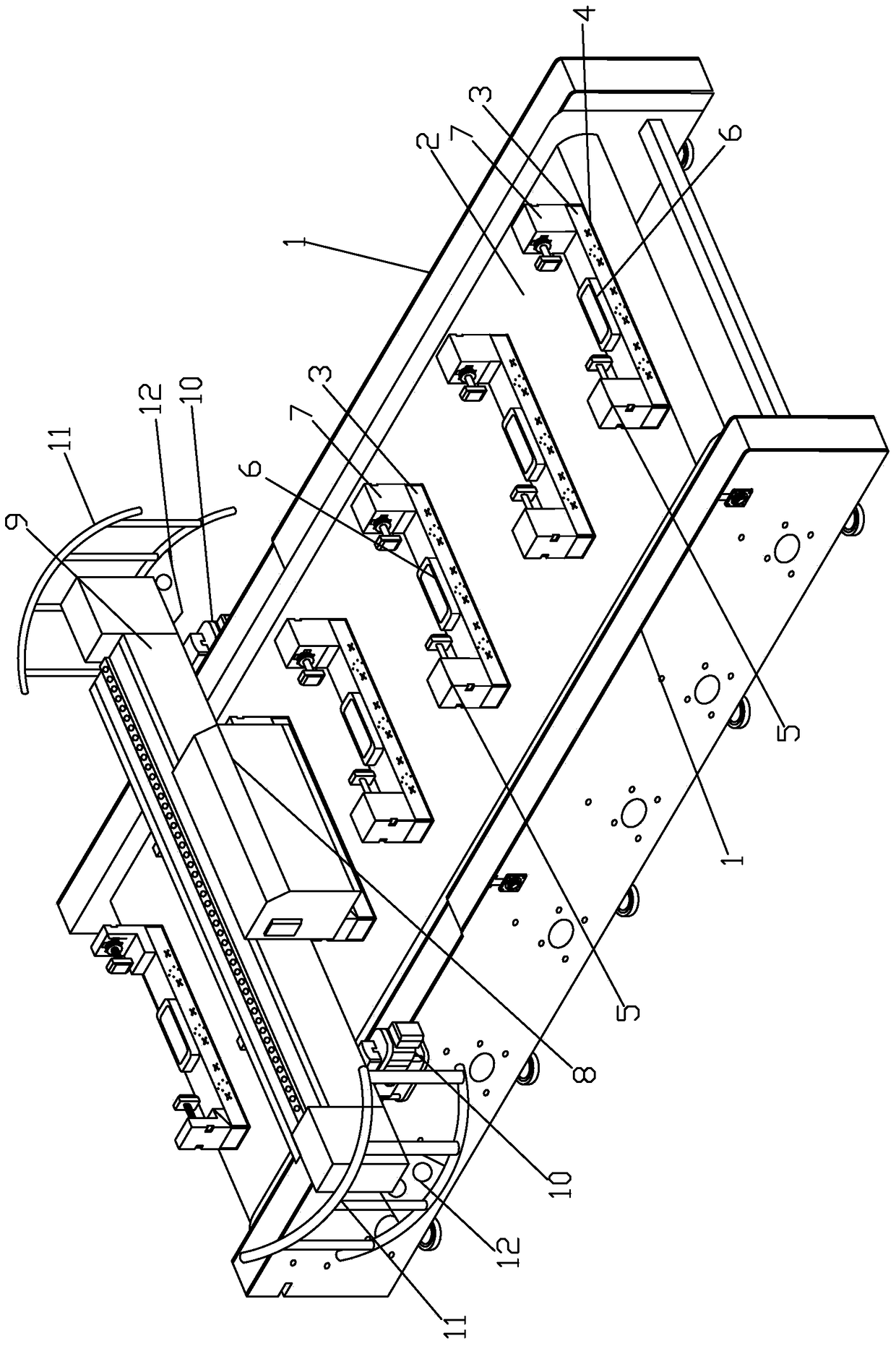
[0033] Such as Figure 1 to Figure 9 As shown, a continuous steel cutting assembly line includes a frame 1, a fixed seat, a cutting device 8 and a beam 9. The frame 1 is 10m long and 1.1m high. There are guide belts 2 and 2 guide belts between the frame 1. Driven by the motor, it can rotate, so that the steel workpiece on the fixed seat can be conveyed by the guide belt 2 at a constant speed, and the steel workpiece can be cut continuously during the conveying process. The cutting effect is high, and the number of steel workpieces that can be cut per unit time increases significantly, which is very suitable for factories Modernized production can bring huge economic and social benefits.

[0034] The guide belt 2 is connected with a fixed seat, which is evenly arranged on the guide belt 2, and the interval between adjacent fixed seats is 1m; the fixed seat includes a base 3, a tray 6 and a positioner, and the lower end of the base 3 is provided with a rubber gasket 4. The base...


PUM


Abstract

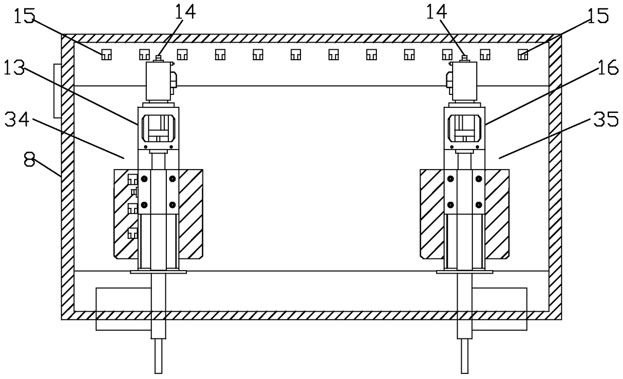
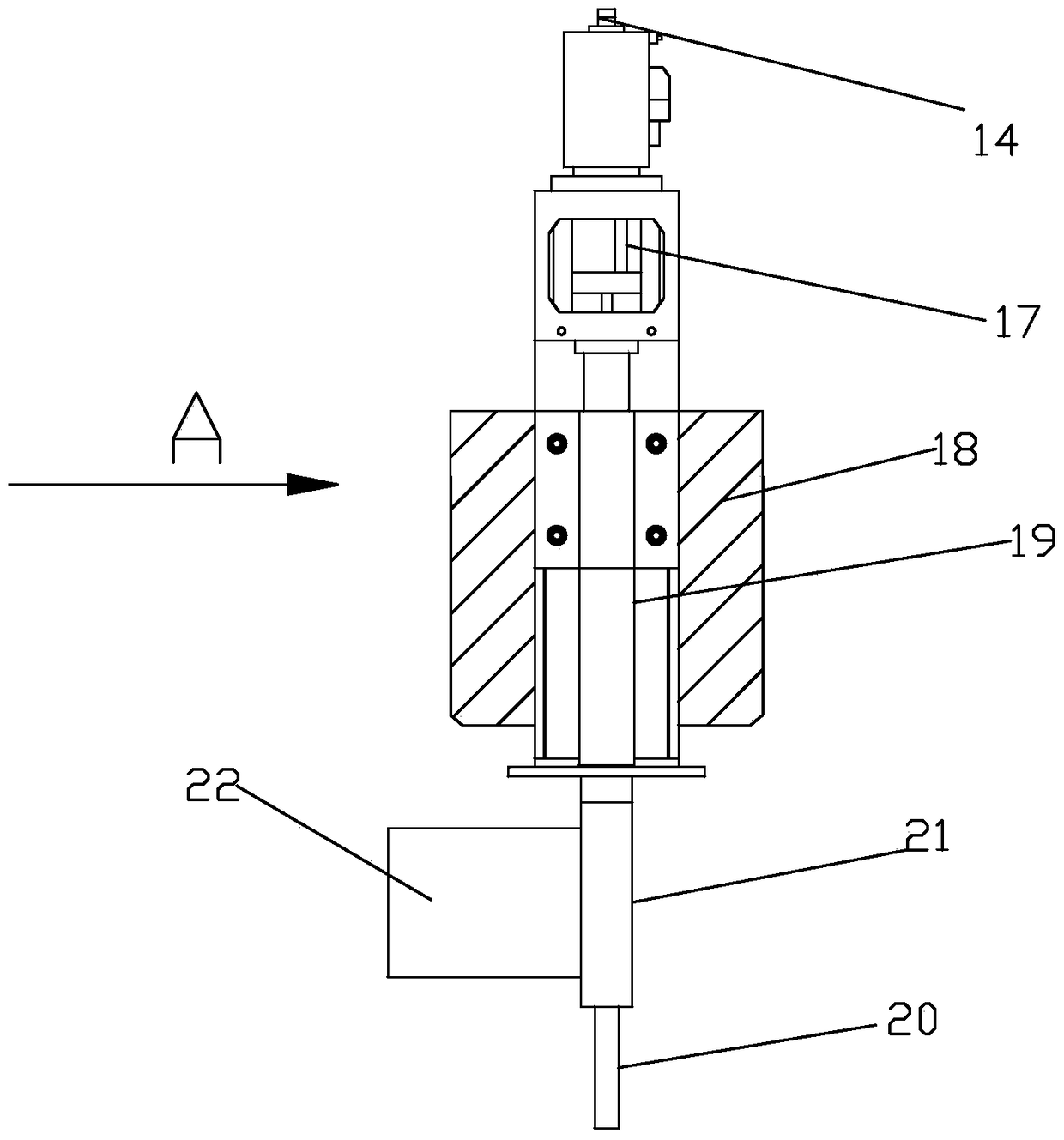
The invention discloses a continuous steel cutting assembly line which comprises racks, fixed seats, a cutting device and a cross beam. A guide belt is arranged between the racks and connected with the fixed seats. The fixed seats comprise bases, trays and locators. Electromagnetic chucks are arranged on the trays, and hydraulic oil cylinders are arranged in the locators, and connected with locating plates. Cutting mechanisms are arranged in the cutting device and comprise lifting sets, connecting blocks and cutters. The upper ends of the lifting sets are connected with induction pieces. Photoelectric sensors are connected in the cutting device, and the induction pieces are matched with the photoelectric sensors. A steam cylinder is arranged in the cross beam and connected with the connecting blocks. Steel workpieces to be cut are continuously conveyed through the guide belt, the steel workpieces are cut in the conveying process, and the aim of continuous cutting is achieved. Compared with a traditional cutting machine, the cutting speed is higher, cutting precision is high, time and labor are saved, no many manpower expenses are needed, the work cost is reduced, and the work environment is safer.

Description

technical field [0001] The invention relates to the field of cutting, in particular to a continuous steel cutting line. Background technique [0002] The world is developing and society is progressing. Since the industrial revolution, mechanical production has been flooding people's social production activities. Cutting machines are also one of the most widely used machines. With the development of modern mechanical processing industries, the quality and accuracy of cutting With continuous improvement, the requirements for improving production efficiency, reducing production costs, and having highly intelligent automatic cutting functions are also increasing. [0003] The traditional cutting machine mainly adopts one-to-one cutting method, which requires workers to assist to complete the cutting operation. This cutting method has the following disadvantages: 1. The cutting machine produces strong noise during the working process and damages the eardrum of the worker, and it ...

Claims


Application Information

Patent Timeline
Patent Type & Authority Patents(China)
IPC IPC(8): B23D19/04B23D33/02B23Q11/06B23Q11/08B23Q5/28B23Q1/01B21D43/20
CPCB21D43/20B23D19/04B23D33/02B23Q1/015B23Q5/28B23Q11/06B23Q11/08
Inventor 屠传伟
Owner 铜陵市旋力特殊钢有限公司
Learn More