System for removing gear burrs

A technology of gears and burrs, applied to components with teeth, belts/chains/gears, gear teeth, etc., to achieve high economic benefits, ensure meshing performance, and simple structure

Inactive Publication Date: 2016-03-16
CHONGQING GUANGDA MACHINERY FACTORY CO LTD
View PDF0 Cites 2 Cited by
  • Summary
  • Abstract
  • Description
  • Claims
  • Application Information

AI Technical Summary

Problems solved by technology

This kind of gear has high load-carrying capacity and efficiency, but it is not as easy to manufacture as the involute gear, and needs to be further improved

Method used


Image

  • System for removing gear burrs

Examples


Embodiment 1

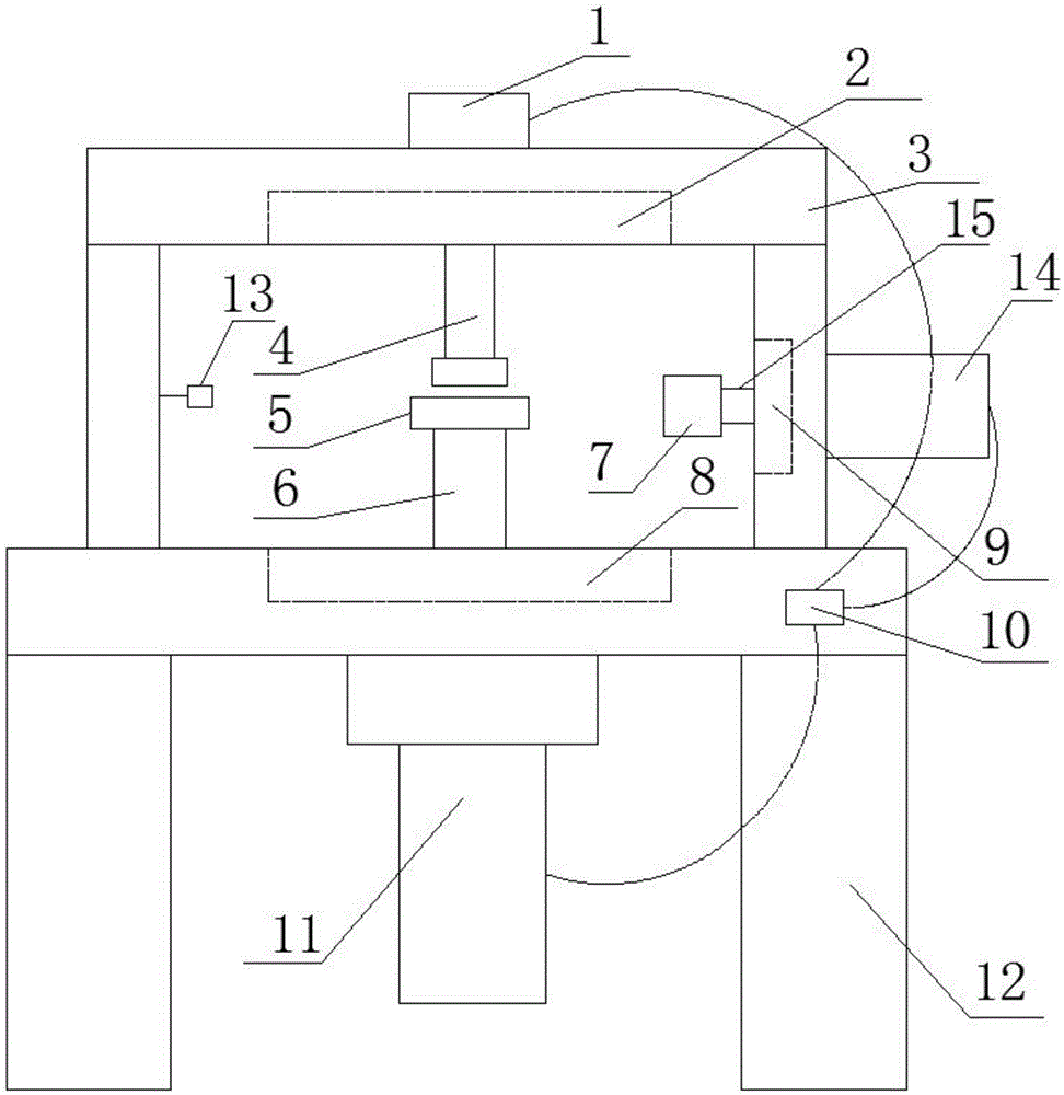
[0028] A system for removing burrs from gears. A device is designed that can be multi-linked to deal with burrs on the gear surface. The three-linkage control method can effectively remove the burrs on the gear surface without affecting the meshing performance of the gears. , has the characteristics of simple structure and high economic benefit, such as figure 1As shown, it is particularly arranged as the following structure: it is provided with an upper bracket system 3 and a lower bracket system 12, and the upper bracket system 3 is fixed on the upper platform of the lower bracket system 12; The gear rotation structure system 11, the rotation shaft 6 of the gear rotation structure system 11 runs through the upper table of the lower support system 12; the push structure system 1 is also arranged on the upper table of the upper support system 3, and the push structure system The rotating shaft 4 of 1 runs through the upper table of the upper bracket system 3, and the rotating ...

Embodiment 2

[0031] This embodiment is further optimized on the basis of the above embodiments. In order to better realize the present invention, it can flexibly control the pushing structure system according to the needs, so that it can move in the horizontal direction so that it can be connected with the brush The system and the gear rotation structure system can cooperate well to remove the burrs on the gears, such as figure 1 As shown, the following structure is particularly arranged: a moving cavity 2 for pushing the structural system 1 to move laterally is also arranged on the upper table. When in use, the pushing structure system 1 can be moved laterally in the moving cavity 2 according to actual needs, so that the brush system 14 can more conveniently remove burrs from the gear 5 .

Embodiment 3

[0033] This embodiment is further optimized on the basis of any of the above-mentioned embodiments. Further, in order to better realize the present invention, it can flexibly control the gear rotation structure system according to the needs, so that it can move in the lateral direction, so that It cooperates well with the brush system and the push structure system to deburr the gears, such as figure 1 As shown, the following structure is particularly arranged: a cavity 8 for the lateral movement of the gear rotation structure system 11 is also provided on the upper table. During use, the gear rotating structure system 11 can be moved laterally in the cavity 8 according to actual needs, so that the brush system 14 can more conveniently remove burrs from the gear 5 .


PUM

PropertyMeasurementUnit
lengthaaaaaaaaaa
diameteraaaaaaaaaa

Abstract

The invention discloses a system for removing gear burrs. The system comprises an upper support system and a lower support system, wherein the upper support system is fixed to an upper table top of the lower support system; a gear rotating structure system is arranged on the lower support system; a rotating shaft of the gear rotating structure system passes through the upper table top of the lower support system; a pushing structure system is also arranged on the upper table top of the upper support system; a spindle of the pushing structure system passes through the upper table top of the upper support system; the rotating shaft is coaxial with the spindle; a brush system is arranged on a side edge support of the upper support system; a moving chamber through which the brush system can move up and down is arranged on the side edge support; a shaft of the brush system passes through the moving chamber, and a brush is arranged on the shaft. According to the system, a device for treating the surface burrs of a gear in a multi-linkage manner is designed; a three-linkage control manner is carried out, so that the burrs on the gear surface can be effectively removed, and moreover, the engaging performance of the gear cannot be influenced.

Description

technical field [0001] The invention relates to the technical field of gear manufacturing, in particular to a system for removing burrs from gears. Background technique [0002] Gear, a mechanical element with teeth on the rim that continuously mesh to transmit motion and power. The application of gears in transmission has appeared very early. At the end of the 19th century, the principle of generative gear cutting method and special machine tools and cutting tools using this principle appeared one after another. With the development of production, the stability of gear operation was paid more attention. [0003] In the west, in 300 BC, the ancient Greek philosopher Aristotle, in "Mechanical Problems", just elaborated the problem of using bronze or cast iron gears to transmit rotary motion. The famous Greek scholars Aristotle and Archimedes have both studied gears. The famous Greek inventor Gutisibios evenly inserted pins on the edge of the circular plate table to make it ...

Claims


Application Information

Patent Timeline
Patent Type & Authority Applications(China)
IPC IPC(8): B23F19/00
CPCB23F19/00
Inventor 王彩虹
Owner CHONGQING GUANGDA MACHINERY FACTORY CO LTD
Why Eureka
Try Eureka