Mechanical processing method of axle bridge for rail vehicle

A technology of mechanical processing and axle bridge, which is applied in the field of rail transit, can solve the problems of large machining allowance, reduced machining efficiency, and poor machining accuracy of the journal surface, so as to solve the large deviation of size and shape and position tolerance, and reduce the machining size and accuracy, shape and position tolerance, and the effect of accuracy stability

Active Publication Date: 2016-03-16
CRRC CHANGZHOU TECH MARK IND CO LTD +1
View PDF4 Cites 10 Cited by
  • Summary
  • Abstract
  • Description
  • Claims
  • Application Information

AI Technical Summary

Problems solved by technology

Due to the irregular shape of the shaft bridge structure, it is difficult to process
Especially when rough turning, finishing turning and grinding are used to process the journal of the axle bridge, since the axle bridge is a large crankshaft part, the center of gravity is not on the center line of the journal, and the journals on both sides of the axle bridge When turning and grinding, it is necessary to rotate the shaft and bridge, so it is easy to generate a large centrifugal force, resulting in poor machining accuracy of the journal surface, and the coaxiality does not meet the requirements
Although most of the centrifugal force can be offset by the counterweight method, it is difficult to grasp the size and position of the counterweight due to the irregular structure of the axle bridge. The machining allowance is large, not only the tool consumption is large, especially the grinding amount usually needs to exceed 1mm, which reduces the processing efficiency
However, a large machining allowance cannot solve the influence of centrifugal force on machining accuracy, and the eccentric rotation will cause large deviations in the size and shape and position tolerances of the machined products, which makes the qualified rate of machined products not high.

Method used


Image

  • Mechanical processing method of axle bridge for rail vehicle
  • Mechanical processing method of axle bridge for rail vehicle
  • Mechanical processing method of axle bridge for rail vehicle

Examples


Embodiment Construction

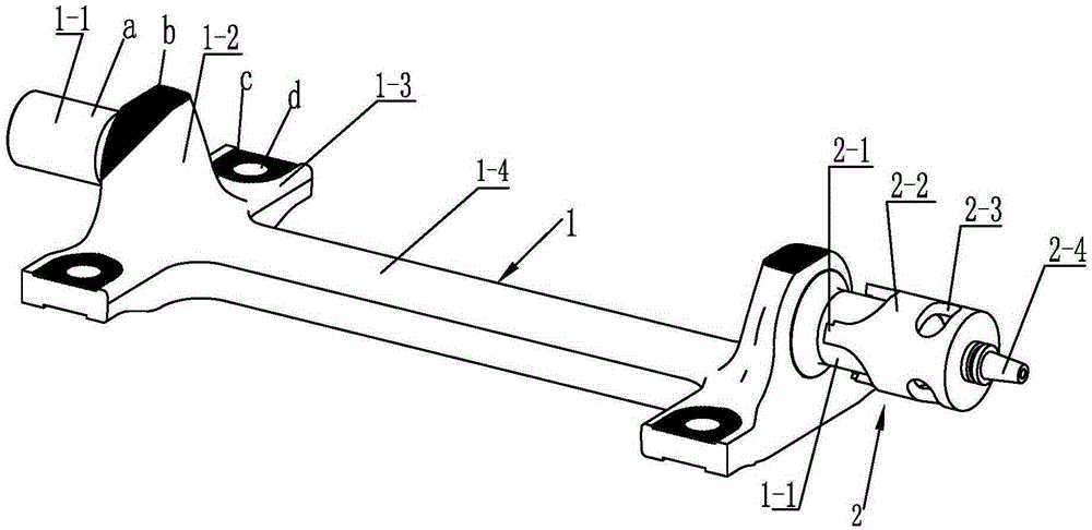
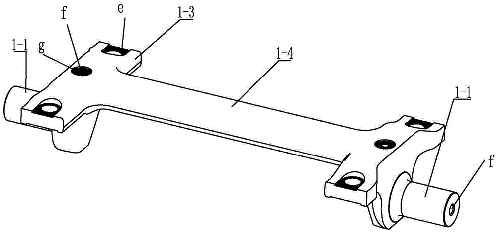
[0023] See figure 1 , 2 Shown, the machining method of the rail vehicle axle bridge of the present invention, carries out according to the following steps,

[0024] ⑴, punch the center hole.

[0025] The bottom surface of the axle bridge blank or the bottom surface of each mounting seat is used as the positioning surface, the axle bridge blank is clamped on the machine tool, and the center hole f is punched on the end faces of the two journals 1-1. A CNC lathe or milling machine can be used to drill a center hole f on the end faces of the two journals 1-1. The center hole f is the thimble hole required for rough machining, and keep the centerlines of the two journals 1-1 coaxial .

[0026] ⑵, rough processing.

[0027] Use two thimbles on the machine tool to prop up the center hole f corresponding to the end face of the journal 1-1 to position the blank of the axle bridge. A horizontal lathe can be used to clamp the blank of the axle bridge, and the turning journal 1-1 can...


PUM


Abstract

The invention relates to a mechanical processing method of an axle bridge for a rail vehicle. The method comprises the following steps: (1) treating the bottom surface of an axle bridge blank as a positioning surface, and clamping; drilling central holes in the end surfaces of two shaft necks; (2) ejecting ejector pins into the central holes in the shaft necks; roughly turning the outer circumferences of the rotating shaft necks; roughly milling the bottom surface of each mounting seat and the bottom surface of each shaft head, and drilling holes in the bottom surfaces; roughly milling the top parts of the shaft heads and the upper end of each mounting seat; (3) modifying the central holes in the two ends of the shaft necks after stress-relieving treatment; (4) positioning and clamping in central holes in the two ends of a semi-finished axle bridge through the ejector pins on a machine tool; performing fine turning for outer circles of the shaft necks; performing fine milling for the planes of the bottom parts of the mounting seats, and reaming; (5) clamping the semi-finished axle bridge on the mounting seats of the machine tool; driving two coaxial grinding cutting tools to rotate through an output shaft of the machine tool so as to enable an empty chamber of a forward-moving barrel-shaped tool body to gradually sleeve the corresponding shaft neck; cutting the outer circle of each shaft neck through a blade until the specified size is reached, so as to obtain the finished axle bridge. With the adoption of the method, the axle bridge processing precision can be improved, and the processing efficiency and product qualification ratio can be improved.

Description

technical field [0001] The invention relates to a machining method for a rail vehicle axle bridge, which belongs to the technical field of rail transportation. Background technique [0002] New modern low-floor rail vehicles require the use of axle and bridge components in order to lower the vehicle floor to around 350 mm. As an important part of the bogie of a low-floor vehicle, the axle bridge supports the weight of the entire car body. The independent wheels connected at both ends of the axle bridge rotate independently under the drive of the motor to drive the vehicle. In order to ensure the safety and comfort of vehicle operation, there are high requirements on the structural performance of the axle bridge and the assembly accuracy with the independent wheels. See figure 1 The shaft bridge 1 (or called a bent shaft) with an integrated structure as shown includes a shaft body, a shaft head 1-2 arranged vertically at both ends of the shaft body, and a shaft journal 1-1 ...

Claims


Application Information

Patent Timeline
Patent Type & Authority Applications(China)
IPC IPC(8): B23P15/00
CPCB23P15/00B61F5/52
Inventor 吴志强戚援宁烨刘建新候传伦蒋涛
Owner CRRC CHANGZHOU TECH MARK IND CO LTD
Why Eureka
Try Eureka