Device for replacing traction friction type anchoring hanger rod and method for replacing steel tube arch bridge hanger rod by using device

An anchoring device and friction-type technology, applied in the field of bridge construction equipment, can solve the problems of high construction cost, steel structure arch rib and coating damage, complicated construction procedures, etc., and achieve low construction cost, high work efficiency, and easy standardized construction. Effect

Active Publication Date: 2016-03-16
LIUZHOU OVM ENG
View PDF6 Cites 6 Cited by
  • Summary
  • Abstract
  • Description
  • Claims
  • Application Information

AI Technical Summary

Problems solved by technology

[0002] At present, most of the suspension rod replacement devices of steel pipe concrete arch bridges are mainly temporary suspension rods or temporary hoisting devices. The upper part of the arch needs to be welded to fix the leveling wedge or anti-slip stop to achieve the leveling of the arch and facilitate the installation of beams. Or the purpose of anti-slip; when the temporary suspender or the temporary hoisting device needs to be transferred to the next suspender replacement place, the beam on the arch needs to be hoisted by large-scale lifting equipment. The disadvantages are: the engineering work is intensive and the welding quality is difficult to control , it is easy to damage the original steel pipe concrete arch rib and coating, the wedge block cannot be used repeatedly, the progress of demolition and restoration work is slow, the consumption of large lifting equipment is large, and the construction cost is high
[0003] The application publication number is: CN102926332A, and the name of the invention is "tool hanger device and replacement method for steel arch bridge hanger replacement" which discloses a tool hanger device for steel arch bridge hanger replacement. Weld the limit device near the location of each suspender replacement. It is difficult to control the welding quality on site. It will damage the arch rib and coating of the original steel structure. The material of the limit device cannot be used for turnover. After the suspender is replaced, local welding on the surface of the steel structure is required. The position of the site is repaired; the number of wire ropes around the arch circle is large, the construction process is complicated, the engineering work intensity is high, the progress of demolition and restoration work is slow, the consumption of large lifting equipment is large, and the construction cost is high

Method used


Image

  • Device for replacing traction friction type anchoring hanger rod and method for replacing steel tube arch bridge hanger rod by using device
  • Device for replacing traction friction type anchoring hanger rod and method for replacing steel tube arch bridge hanger rod by using device
  • Device for replacing traction friction type anchoring hanger rod and method for replacing steel tube arch bridge hanger rod by using device

Examples


Embodiment 1

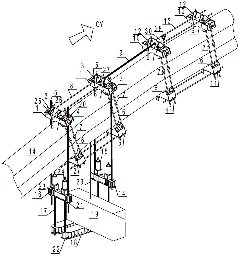
[0049] A traction friction type anchor boom replacement device, such as figure 1 , 2 As shown, the device for replacing the traction friction anchor boom includes steel strand fixed end anchors I, II, III, steel strand tension end anchors I, II, upper conversion beam 16, upper steel strand 5 1. In addition to the lower steel strand wire 17 and the lower joist 18, it also includes a traction friction anchorage arch anchorage anti-skid system installed on the arch bridge arch of steel pipe concrete;

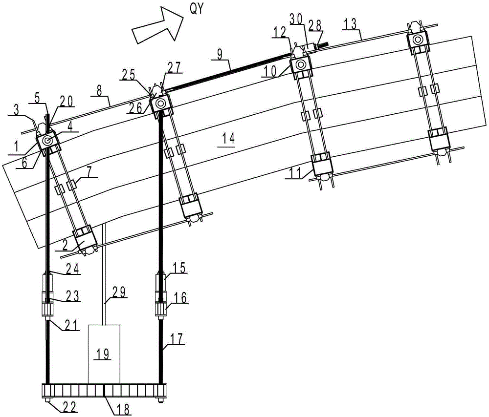
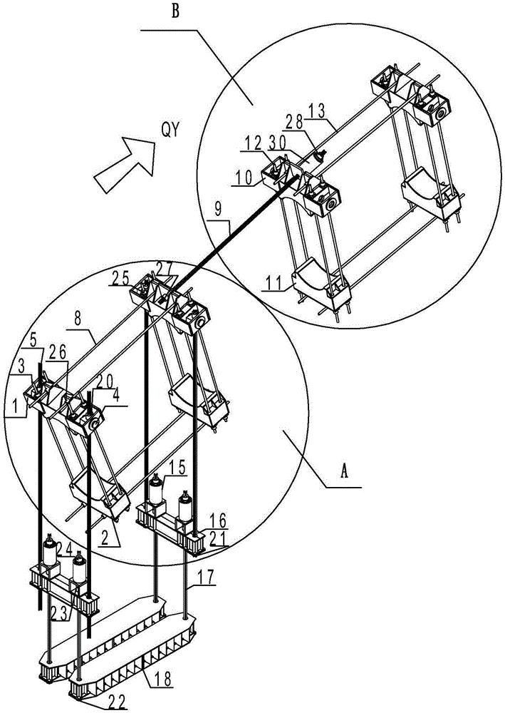
[0050] like image 3 , Figure 4 As shown, the traction friction anchoring arch anchoring anti-skid system consists of a traction cable 9, a traction cable fixed end anchor 27, a traction cable tension end anchor 28, a horse-riding upper clamping device I1, a horse-riding lower clamping device Ⅰ2, rotary spreader 4, pre-tightened threaded steel Ⅰ3, tie rod Ⅰ8, saddle-style upper clamping device Ⅱ10, saddle-riding lower clamping device Ⅱ11, pre-tightened rebar Ⅱ12, tie rod Ⅱ13 、...

Embodiment 2

[0056] A method for replacing the suspension rod of a steel pipe arch bridge, which is a method for replacing the suspension rod of a steel pipe arch bridge using the device for replacing the traction friction anchor suspension rod described in Embodiment 1, and it includes the following steps:

[0057] A. Install the device for replacing the traction friction anchor boom: (see Figure 1-Figure 6 )

[0058] A1. The steel pipe arch 14 is longitudinally symmetrical to the original suspender 29 and the traction friction anchoring arch anchoring anti-skid system is installed on the steel pipe arch 14:

[0059] The traction friction anchoring arch anchoring anti-skid system consists of a traction cable 9, a traction cable fixed end anchor 27, a traction cable tension end anchor 28, a horse-riding upper clamping device I1, a horse-riding lower clamping device I2, a rotating Type spreader 4, pre-tightened rebar Ⅰ3, pull rod Ⅰ8, saddle-type upper clamping device Ⅱ10, equestrian-type ...


PUM


Abstract

The invention discloses a device for replacing a traction friction type anchoring hanger rod. The device comprises a fixed end anchoring tool, a stretching end anchoring tool, an upper transfer girder, upper and lower steel strands, a lower supporting beam, and a traction friction anchored type arch top anchoring skid resisting system which is mounted on an arch of an arch bridge, wherein the arch top anchoring skid resisting system comprises a friction anchoring device I consisting of two groups of upper and lower riding type clamping devices I and two pull rods I, and a friction anchoring device II consisting of two upper and lower riding type clamping devices II and two pull rods II; the two ends of a pulling cable are respectively anchored on the upper riding type clamping devices I or the upper riding type clamping devices II; a pulling jack is driven to stretch the pulling cable to realize skid resistance of the traction type arch top friction anchoring skid resisting system; four rotary lifting tools for levelling are respectively positioned at the two ends of the two upper riding type clamping devices I and the two upper riding type clamping devices II and rotate through pin shafts so as to adaptively realize levelling of the lifting tools; according to the device, small influences are caused to stress of an original structure during a cable force transfer process of hanger rod replacing; convenience is provided for standard construction; high work efficiency is realized.

Description

technical field [0001] The invention relates to a bridge construction machine tool, in particular to a tool hanger device for replacing the hanger of a steel pipe truss concrete arch bridge and a method for replacing the hanger of a steel pipe arch bridge. Background technique [0002] At present, most of the suspension rod replacement devices of steel pipe concrete arch bridges are mainly temporary suspension rods or temporary hoisting devices. The upper part of the arch needs to be welded to fix the leveling wedge or anti-slip stop to achieve the leveling of the arch and facilitate the installation of beams. Or the purpose of anti-slip; when the temporary suspender or the temporary hoisting device needs to be transferred to the next suspender replacement place, the beam on the arch needs to be hoisted by large-scale lifting equipment. The disadvantages are: the engineering work is intensive and the welding quality is difficult to control , It is easy to damage the original...

Claims


Application Information

Patent Timeline
Patent Type & Authority Applications(China)
IPC IPC(8): E01D22/00
CPCE01D22/00
Inventor 窦勇芝韦福堂甘科孙长军黎祖金
Owner LIUZHOU OVM ENG
Why Eureka
Try Eureka