High-efficiency thermodynamic cycle system using vortex tubes

A thermal cycle system, vortex tube technology, applied in lighting and heating equipment, steam engine devices, compressors, etc., can solve the problems of low thermal cycle efficiency, reduced compression work, large compression work, etc., to improve the net efficiency, circulation High efficiency, reducing the effect of compression work

Active Publication Date: 2018-05-01
DEZHOU GAOKELI HYDRAULIC
View PDF5 Cites 0 Cited by
  • Summary
  • Abstract
  • Description
  • Claims
  • Application Information

AI Technical Summary

Problems solved by technology

[0004] The present invention provides a high-efficiency thermodynamic cycle system using vortex tubes to solve the problems of heat loss in the cooling process of the working fluid in the prior art, large compression work in the compression process, and low thermal cycle efficiency. The vortex tube cooling method is adopted. No external work is consumed, high-temperature heat can be recycled, no heat is lost to the outside world, and the cooling and liquefaction of the gaseous working medium after expansion and work can be realized. The use of a liquid working medium pump reduces the compression work and improves the cycle thermal efficiency of the system.

Method used


Image

  • High-efficiency thermodynamic cycle system using vortex tubes
  • High-efficiency thermodynamic cycle system using vortex tubes

Examples


Embodiment Construction

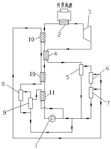
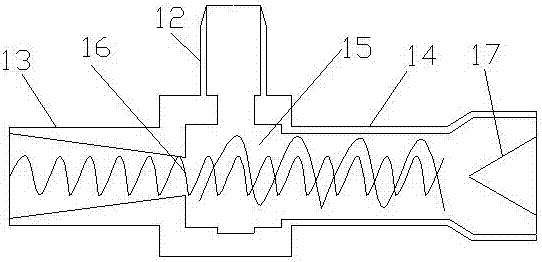
[0013] Such as figure 1 and figure 2 As shown, a high-efficiency thermodynamic cycle system using a vortex tube is mainly composed of a working medium pump 1, a heat exchanger 2 and an expander 3. The outlet of the working medium pump 1 is connected to the expander 3 through the heat exchanger 2, and the expansion A cooling unit is arranged between the engine 3 and the working medium pump 1, the cooling unit is a vortex tube split flow cooling unit, the vortex tube split flow cooling unit includes a five-stage vortex tube combination, the vortex tube is a very simple energy separation device, and it consists of Nozzle 12, vortex chamber 15, separation orifice 16, low-temperature end pipe 13, high-temperature end pipe 14 and regulating valve 17, the low-temperature liquid working fluid separated by the first-stage vortex tube 5 and the third-stage vortex tube 7 enters the working medium pump The inlet of 1, the high-temperature gaseous working medium separated by the second-s...


PUM


Abstract

The high-efficiency thermodynamic cycle system using vortex tubes is mainly composed of working fluid pumps, heat exchangers, expanders and vortex tube split cooling units. The vortex tube split cooling unit is composed of several vortex tubes. The liquid working medium separated by the vortex tube directly enters the inlet of the working medium pump, and the gaseous working medium enters the heat exchanger to exchange heat with the low-temperature working medium on the high-pressure side of the circulation system. The working medium enters the vortex tube again for split cooling, the liquid working medium enters the inlet of the working medium pump, and the gaseous working medium enters the heat exchanger again to exchange heat with the low-temperature working medium on the high-pressure side of the circulation system. After multi-stage vortex tube split cooling and multiple heat exchanges with low-temperature working fluid, most of the working fluid enters the inlet of the working fluid pump in liquid form, and only a very small part of the working fluid is not liquefied. The ratio of the two is appropriate, and the two The combination can ensure that all the working fluid at the inlet of the working fluid pump is in liquid state. The invention uses a liquid working medium pump to pressurize the working medium, the power consumption of the pump is reduced, and the heat in the circulation system is recovered and utilized, and the thermal efficiency is high.

Description

technical field [0001] The invention relates to the fields of heat cycle utilization technology and vortex tube cooling technology, in particular to a high-efficiency thermodynamic cycle system using a vortex tube. Background technique [0002] The high-efficiency thermodynamic cycle system using the vortex tube is a thermodynamic cycle system based on the Rankine cycle. The Rankine cycle refers to an ideal cycle process using water vapor as a working medium, mainly including isentropic compression, isobaric heating, isentropic expansion, and an isobaric condensation process, and is mainly used in the power cycle of steam plants. At present, the Rankine cycle thermodynamic systems researched and developed at home and abroad include organic Rankine cycle and supercritical Rankine cycle. The organic Rankine cycle is a Rankine cycle with low-boiling point organic matter as the working medium, and the supercritical Rankine cycle is a Rankine cycle with supercritical fluid as th...

Claims


Application Information

Patent Timeline
Patent Type & Authority Patents(China)
IPC IPC(8): F01K19/10F25B9/04
CPCF01K19/10F25B9/04
Inventor 靳宗宝刘焕英
Owner DEZHOU GAOKELI HYDRAULIC
Why Eureka
Try Eureka