Gas turbine power generation device acting through pulse detonation fuel gas viscous force

A technology of pulse detonation and gas turbines, which is applied in the direction of gas turbine devices, deflagration combustion chambers, machines/engines, etc., and can solve the problems of low energy conversion efficiency of pulse detonation gas, influence of detonation combustion wave pressure back transmission, and detonation gas energy. Low conversion efficiency and other issues, to achieve the effect of improving cycle thermal efficiency, fast flame propagation speed, and reducing the number of stages

Active Publication Date: 2020-08-25
XIAN THERMAL POWER RES INST CO LTD
View PDF11 Cites 3 Cited by
  • Summary
  • Abstract
  • Description
  • Claims
  • Application Information

AI Technical Summary

Problems solved by technology

[0005] In order to solve the problems that occur after the pulse detonation combustion chamber is replaced by the isobaric combustion chamber in the power generation power plant such as a ground gas turbine, such as the low conversion efficiency of detonation gas energy, the reverse transmission of detonation combustion wave pressure affecting the operation of the compressor, etc., the present invention Propose a gas turbine power generation device using the viscous force of pulse detonation gas to do work
Since the Tesla turbine does not have any blade structure, compared with the axial flow and centripetal turbines used in the existing power plant, the unsteady pulse detonation gas can be adaptively generated in the Tesla turbine in a transient viscous Energy conversion by means of force action, solving the problem of low energy conversion efficiency of axial flow and centripetal turbines for pulse detonation gas
At the same time, the present invention aims at the working characteristics of the pulse detonation combustion chamber, and proposes a pneumatic valve structure that can adaptively follow the change of the working frequency of the pulse detonation combustion chamber. By using the pressure difference between the intake air and the detonation combustion wave back-transmission pressure difference, the automatic Open and close the pneumatic valve to solve the problem of detonation combustion wave pressure back propagation affecting the operation of the compressor

Method used


Image

  • Gas turbine power generation device acting through pulse detonation fuel gas viscous force

Examples


Embodiment Construction

[0024] The specific embodiments of the present invention will be described in detail below with reference to the accompanying drawings.

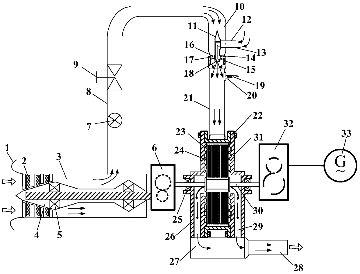
[0025] See figure 1 As shown, the gas turbine involved in this embodiment has a compressor rotor 4, an intake duct 1, a compressor 2, and a gas storage chamber 3 and a compressor exhaust pipe 8 that are annularly mounted on the outside of the rotor 4, rotating around a rotating shaft. , Combustion chamber inlet 10, combustion chamber inlet cone 11, combustion chamber pneumatic valve 14, pulse detonation combustion chamber 21, Tesla turbine 22 and exhaust pipe 28, and form such figure 1 The middle arrow shows the gas flow path through them.

[0026] In the direction of the gas turbine's airflow, the inlet port 1 is placed at the forefront of the gas turbine, and the compressor 2 is connected to the inlet port 1. As knock combustion has the advantage of self-supercharging, the number of compressor stages in this example only needs to be 2 to 3 Th...


PUM


Abstract

The invention discloses a gas turbine power generation device acting through pulse detonation fuel gas viscous force. The gas turbine power generation device comprises a gas inlet channel, a gas compressor and the like. The gas inlet channel is located at the forefront end of a gas turbine, the gas compressor is connected with the gas inlet channel, and a gas storage chamber is arranged on the downstream portion of the gas compressor. An exhaust pipe of the gas compressor is connected with the gas storage chamber and a combustion chamber gas inlet channel. A combustion chamber gas inlet cone is arranged in the combustion chamber gas inlet channel, and a combustion chamber pneumatic valve is mounted on the combustion chamber gas inlet cone. A pulse detonation combustion chamber is connectedwith the combustion chamber gas inlet channel, a spark plug is arranged on the head of the pulse detonation combustion chamber, and a telsa turbine is arranged at an outlet of the pulse detonation combustion chamber. A gas collection cavity is arranged on the side of the telsa turbine. The exhaust pipe is connected with the gas collection cavity. The left end of a gas compressor transmission is connected with a gas compressor rotor, and the right end of the gas compressor transmission is connected with a turbine rotor. The left end of a generator transmission is connected with the turbine rotor, and the right end of the generator transmission is connected with a generator. According to the gas turbine power generation device, the problems happening after the pulse detonation combustion chamber replaces an isobaric combustion chamber in a ground gas turbine and other power generation power devices are solved.

Description

Technical field [0001] The invention relates to a gas turbine, in particular to a gas turbine power generation device that utilizes the viscous force of pulse detonation gas to perform work, and is applied to convert low-quality fuel heat release internal energy into high-quality electric energy. Background technique [0002] Slow-burning combustion is a combustion method that heats the combustible mixture through heat conduction, thermal diffusion, and thermal radiation and causes a chemical reaction. The flame propagation speed is small, often less than 1m / s. At present, power plants such as ground gas turbines, naval gas turbines, aero engines, and missile engines often use isobaric combustion chambers based on the slow combustion method. During the fuel combustion process, the gas pressure in the combustion chamber is basically unchanged or slightly reduced, and the performance of this type of power plant has developed to a relatively mature stage. The ideal cycle thermal ef...

Claims


Application Information

Patent Timeline
Patent Type & Authority Applications(China)
IPC IPC(8): F02C5/00F02C6/00F01D1/32F23R7/00
CPCF02C5/00F02C6/00F01D1/32F23R7/00F02C3/04F05D2220/76F05D2240/35F23R3/28
Inventor 李晓丰肖俊峰王玮王峰胡孟起段静瑶
Owner XIAN THERMAL POWER RES INST CO LTD
Why Eureka
Try Eureka