Fully permanent magnetic floating wind generator

A wind turbine and maglev technology, which is applied in wind turbine components, wind turbines, wind energy power generation and other directions, can solve the problems of not being widely applicable to the field of wind power generation, critical maintenance and application environment, complex control system, etc., to achieve the expansion of effective wind speed Scope, low cost, effect of great economic and social value

Active Publication Date: 2007-09-12
湖南终南山科技发展有限公司
View PDF0 Cites 34 Cited by
  • Summary
  • Abstract
  • Description
  • Claims
  • Application Information

AI Technical Summary

Problems solved by technology

The current magnetic levitation wind turbines, such as the electromagnetic levitation wind turbines in the United States, need to control the levitation bearings in all degrees of freedom, so the control system is extr

Method used


Image

  • Fully permanent magnetic floating wind generator
  • Fully permanent magnetic floating wind generator
  • Fully permanent magnetic floating wind generator

Examples


Embodiment Construction

[0029] The present invention will be further described below in conjunction with accompanying drawing.

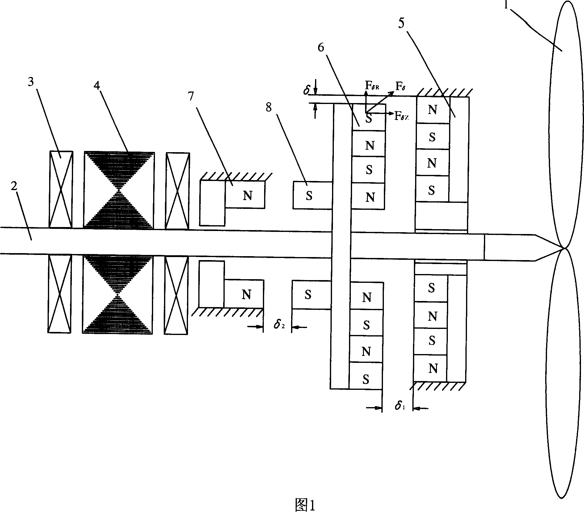
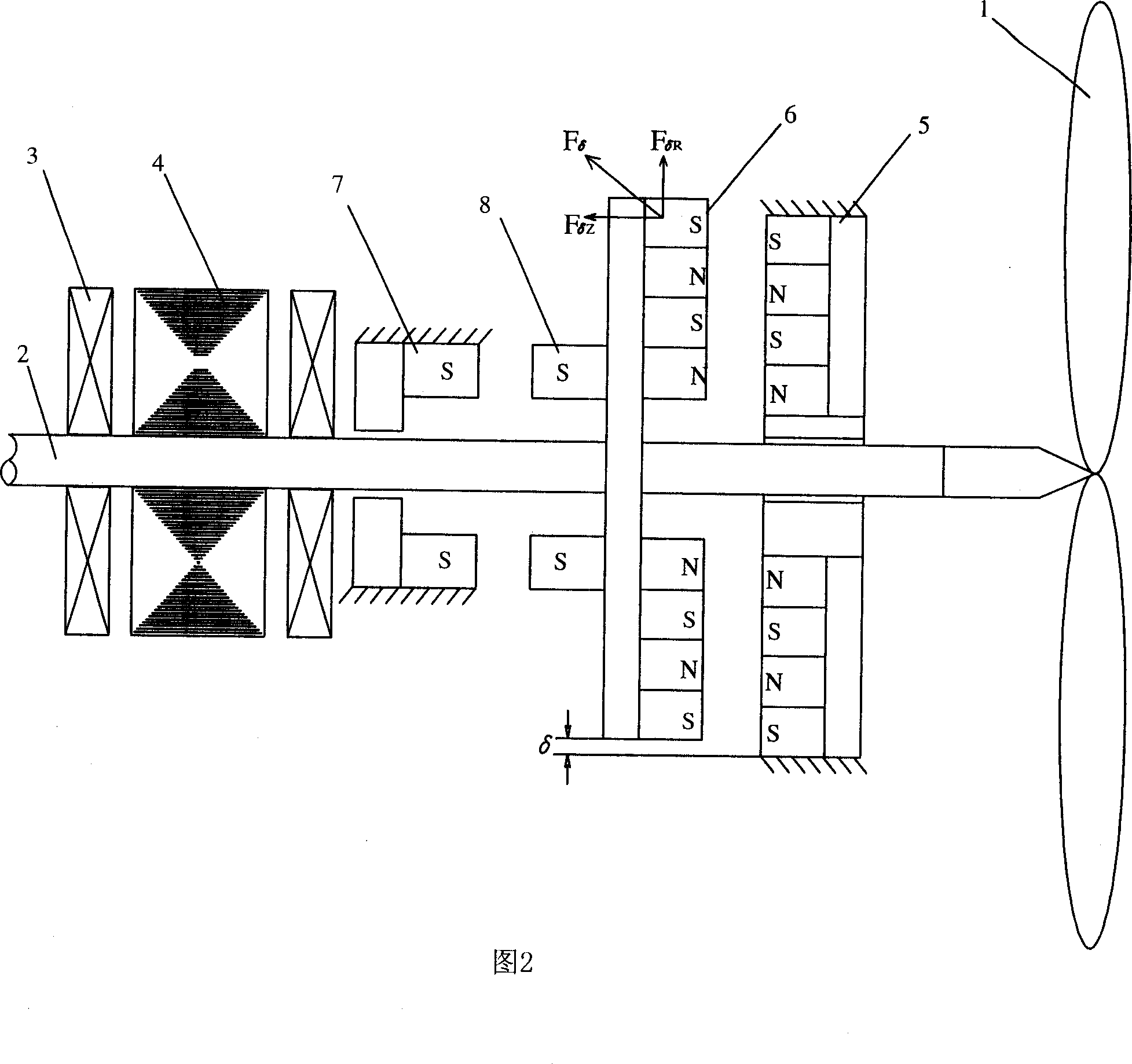
[0030] As shown in Figure 1, it is an embodiment of the present invention.

[0031] A traditional wind power generating set includes an impeller 1, a shaft 2, a mechanical bearing 3, and a generator 4, wherein the impeller 1 is generally arranged at one end of the shaft 2, the generator 4 is arranged at the other end of the shaft 2, and the two ends of the generator 4 are respectively arranged There are mechanical bearings3. Since the direction of the wind force is variable, the angle of the impeller 1 needs to be constantly changed to face the wind direction, and the shaft 2 is arranged on the frame through a mechanical rotating device.

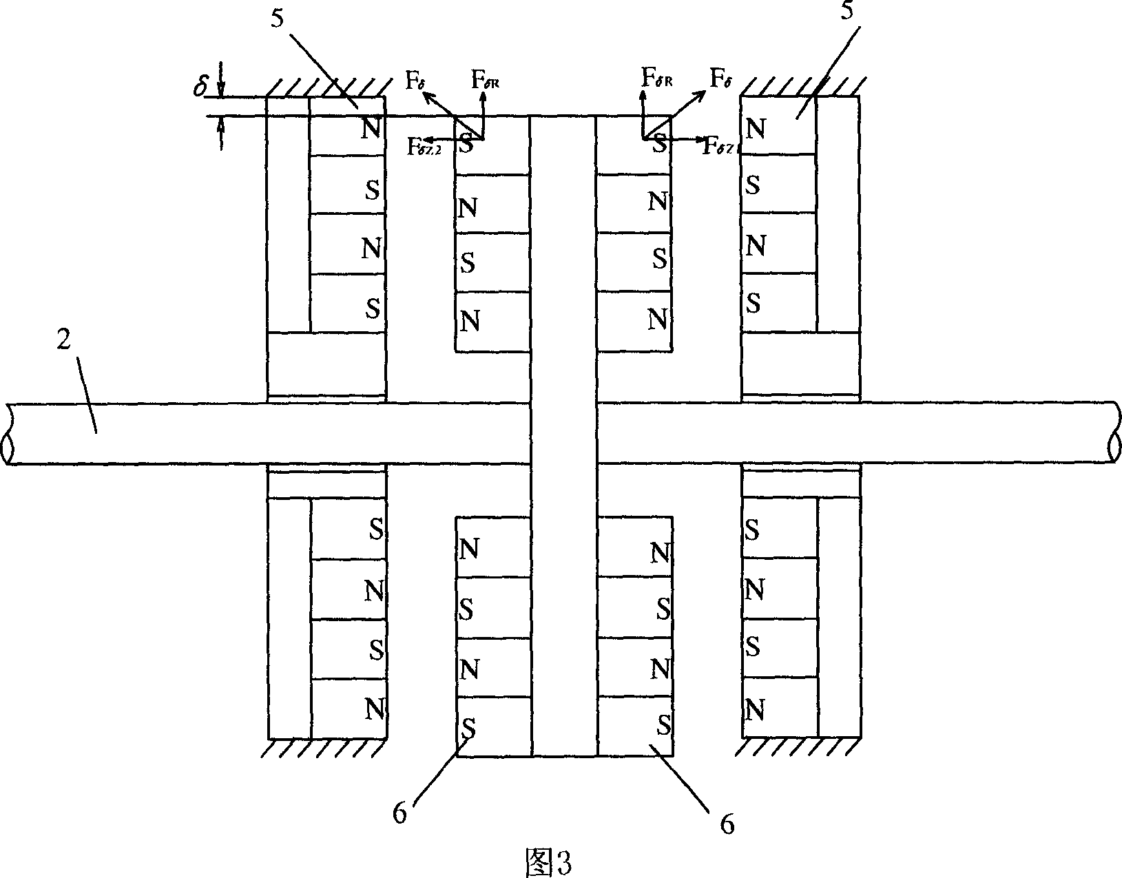
[0032] Such a shaft structure is a typical cantilever beam structure. The shaft 2 will produce a certain amount of flexible deformation under the influence of the gravity of the impeller 1, and a non-axial force will be generated on the ...


PUM


Abstract

The invention provides an all-PM suspension wind power generator, comprising frame, mechanical bearing, shaft and wind turbine, where the wind turbine is arranged at the front part of the shaft, the shaft is connected via the mechanical baring with the frame and it is characterized in that: one or more groups of PM suspension devices are arranged between the wind turbine and the mechanical bearing and use the potential difference between the corresponding magnetic poles encircling the shaft and respectively arranged on the shaft and frame to generate upward magnetic force so as to eliminate the effect of the wind turbine gravity.

Description

technical field [0001] The invention relates to wind power generating equipment, in particular to a novel full permanent magnetic levitation micro-friction wind power generator. Background technique [0002] Wind energy is not only clean, environmentally friendly, and renewable, but also widely distributed, ubiquitous, and easy to use. It is a new type of energy with great development prospects. Moreover, people's use of wind power to generate electricity will not only have no negative impact, but will also bring the benefits of mitigating wind disasters, inhibiting desertification, and reducing or reducing the number and intensity of sandstorms. [0003] People have a long history of understanding and utilizing wind energy. In the early days, windmills were mainly used to replace human beings for simple labor such as irrigation and pounding rice. At present, we use wind power to generate electricity, but the wind generated by nature not only changes in wind direction, but a...

Claims


Application Information

Patent Timeline
IPC IPC(8): H02N15/00F16C32/04
CPCF16C2300/14F16C2360/31Y02E10/722F16C39/066F05B2240/51F03D11/0008F03D80/70F16C32/0412F16C32/0425F16C39/063F16C2300/32Y02E10/72
Inventor 李国坤曾智勇谢丹平
Owner 湖南终南山科技发展有限公司
Why Eureka
Try Eureka