
A fuel tank isolation solenoid valve

A technology of solenoid valves and solenoid valve components, applied in valve details, valve devices, valve operation/release devices, etc., can solve problems such as increased system complexity, difficult control of spring cumulative errors, and poor consistency of spring machining

Active Publication Date: 2018-02-06
JIANGSU AOLIWEI SENSING TECH
View PDF5 Cites 0 Cited by
  • Summary
  • Abstract
  • Description
  • Claims
  • Application Information

AI Technical Summary

Problems solved by technology

The mechanical processing consistency of the spring is relatively poor, and the cumulative error of the three springs is more difficult to control
Increased system complexity and decreased product yield

Method used


Image

  • A fuel tank isolation solenoid valve
  • A fuel tank isolation solenoid valve
  • A fuel tank isolation solenoid valve

Examples


Embodiment Construction

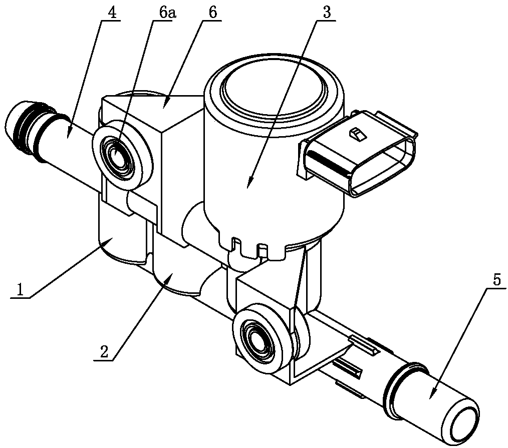
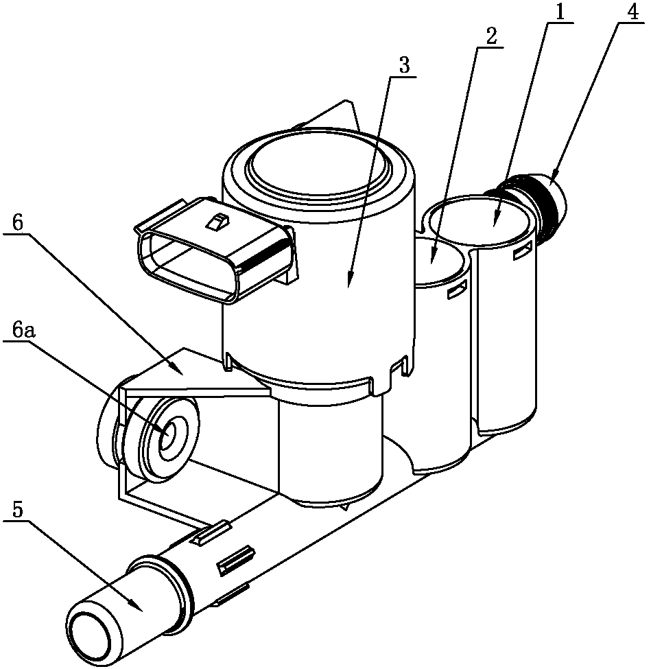
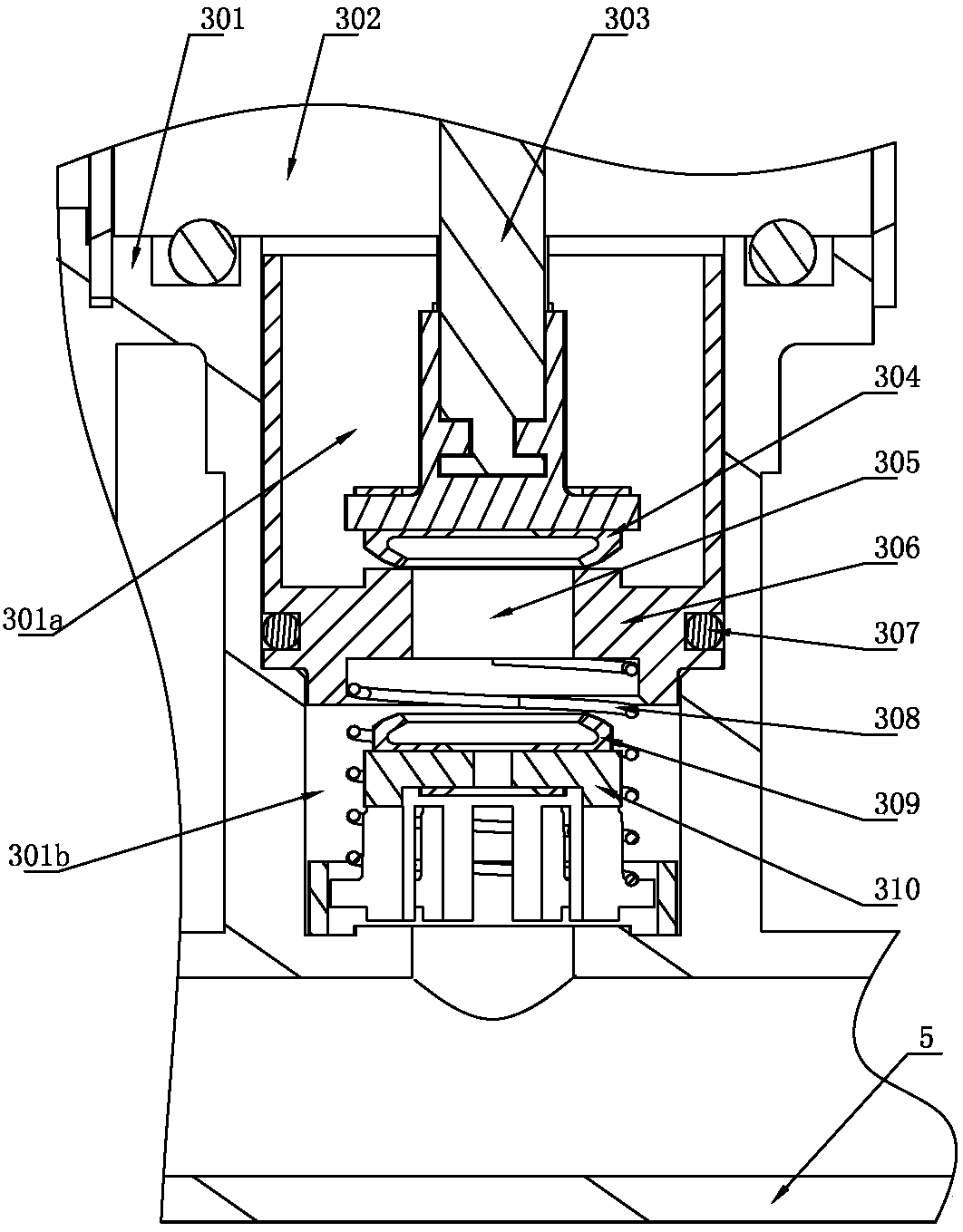
[0023] Such as Figure 1-4 A fuel tank isolation solenoid valve shown includes a fuel tank pipeline 5, a solenoid valve assembly 3, an air release valve assembly 1, an air supply valve assembly 2, and a carbon tank pipe 4, a valve body 301 of the solenoid valve assembly 3, and a valve body 301 of the air release valve assembly 1. The shell and the air supply valve assembly 2 are integrally formed. The bottoms of the solenoid valve assembly 3, the air release valve assembly 1, and the air supply valve assembly 2 are all connected to the fuel tank pipeline 5 to form a gas path communication. The solenoid valve assembly 3. The upper parts of the air release valve assembly 1 and the air supply valve assembly 2 are connected to the carbon tank pipeline 4 and form a gas path communication. The solenoid valve assembly 3, air release valve assembly 1, and air supply valve assembly 2 are connected to each other The casings are connected together; the solenoid valve assembly 3 includes ...


PUM


Abstract

The invention discloses a fuel tank isolation electromagnetic valve in the field of valves. The fuel tank isolation electromagnetic valve comprises a fuel tank pipeline, an electromagnetic valve assembly, a snuffle valve assembly, a gulp valve assembly and a charcoal canister pipeline, wherein bottoms of the electromagnetic valve assembly, the snuffle valve assembly and the gulp valve assembly are all connected onto the fuel tank pipeline, and gas circuits are formed and communicated with the fuel tank pipeline; the upper portions of the electromagnetic valve assembly, the snuffle valve assembly and the gulp valve assembly are all connected onto the charcoal canister pipeline, and gas circuits are formed and communicated with the charcoal canister pipeline; the electromagnetic valve assembly, the snuffle valve assembly and the gulp valve assembly are connected together through casings among three assemblies; in a refueling process, the electromagnetic valve is turned on, and steam of a fuel tank is discharged into a charcoal canister rapidly in a controlled flow, so that the refueling waiting time is reduced, and the blocking problem of an FLVV (Fill Limit Venting Valve) is avoided as well; and the fuel tank isolation electromagnetic valve can be used in a motor vehicle control system.

Description

technical field [0001] The invention relates to a valve, in particular to an oil tank isolation solenoid valve. Background technique [0002] In a typical evaporative emissions management system, fuel vapors are vented to the carbon canister through the fuel tank GVV valve. The carbon canister contains activated carbon, which has the function of absorbing fuel vapor. When the engine is started, fresh air is sucked into the carbon tank, and together with the fuel vapor absorbed by the activated carbon, it is sent to the engine to participate in combustion. However, in plug-in hybrid models, there is a long-term use of electric drive mode driving, and the carbon tank has no desorption function in electric mode. If the steam in the fuel tank has been discharged to the carbon tank, it is easy to cause the carbon tank to be saturated. The saturated fuel vapor will be directly discharged into the environment, causing environmental pollution. Therefore a tank isolation valve is...

Claims


Application Information

Patent Timeline
Patent Type & Authority Patents(China)
IPC IPC(8): F02M25/08B60K15/035F16K39/02F16K31/06
CPCB60K15/035F02M25/08F02M2025/0845F16K31/06F16K39/02
Inventor 顾常飞孙海鑫俞斌强李冬梅糜帅
Owner JIANGSU AOLIWEI SENSING TECH
Learn More