
System and method for measuring battery level

A battery power and battery technology, applied in the direction of measuring electrical variables, measuring electricity, measuring devices, etc., can solve the problems of increasing the space occupied by mobile phones, power jumps, increasing production costs, etc., to achieve accurate measurement and display, and improve power accuracy , the effect of saving space

Active Publication Date: 2016-03-16
SPREADTRUM COMM SHENZHEN CO LTD
View PDF5 Cites 16 Cited by
  • Summary
  • Abstract
  • Description
  • Claims
  • Application Information

AI Technical Summary

Problems solved by technology

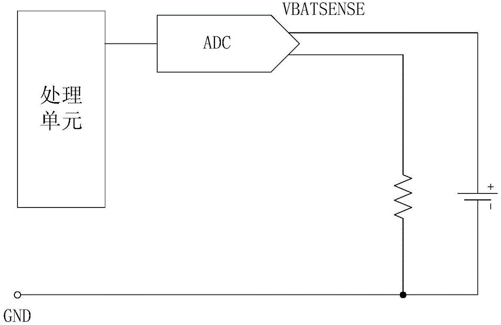
[0002] At present, for the battery power display of low-end mobile phones, the result of voltage measurement by the analog-to-digital converter (ADC) is usually directly used as the power display. , there will be a situation where the power jumps; when the mobile phone is replaced with a battery of a different voltage, because the existing software uses a memory algorithm, the displayed power will not change
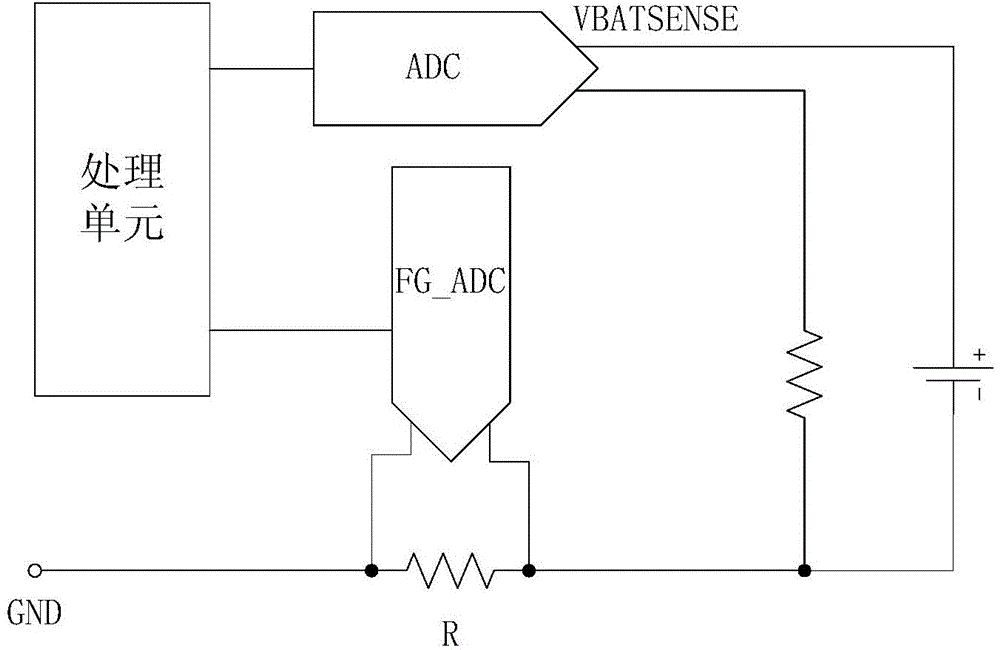
For the measurement of the battery power of high-end mobile phones, an additional power calculation chip is generally used, or an external 20mohm sampling resistor R and an analog-to-digital converter FG_ADC channel (such as figure 1 As shown), the voltage difference V1 is obtained by comparing the difference between the analog-to-digital converter FG_ADC at both ends of the battery and the analog-to-digital converter ADC that comes with the original machine. According to the formula xmA=V1 / 20mohm, the real-time current xmA is obtained by calculation, and then integrated over time T , this method requires two ADCs for continuous sampling calculation, and additional circuits are required, which increases the occupied space of the mobile phone and increases the generation cost

Method used


Image

  • System and method for measuring battery level
  • System and method for measuring battery level
  • System and method for measuring battery level

Examples


Embodiment Construction

[0045] The following will clearly and completely describe the technical solutions in the embodiments of the present invention with reference to the accompanying drawings in the embodiments of the present invention. Obviously, the described embodiments are only some, not all, embodiments of the present invention. Based on the embodiments of the present invention, all other embodiments obtained by persons of ordinary skill in the art without creative efforts fall within the protection scope of the present invention.

[0046] It should be noted that, in the case of no conflict, the embodiments of the present invention and the features in the embodiments can be combined with each other.

[0047] The present invention will be further described below in conjunction with the accompanying drawings and specific embodiments, but not as a limitation of the present invention.

[0048] Such as figure 2 and image 3 As shown, a system for measuring battery power is applied to a mobile te...


PUM


Abstract

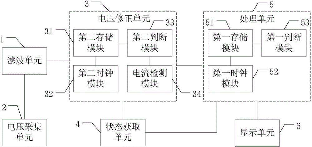
The invention discloses a system and method for measuring a battery level. A voltage collection unit of the system is connected to a preset node of a battery branch, and is used for collecting a voltage across two ends of a to-be-measured battery. A state obtaining unit is used for obtaining the current operation state of a mobile terminal. A voltage correction unit is used for connecting the voltage collection unit and the state obtaining unit, and is used for correcting the collected voltage according to the current operation state of the mobile terminal and outputting the corrected voltage. The processing unit is connected with the voltage correction unit and the state obtaining unit, and is used for calculating electric quantity data according to the corrected voltage outputted by the voltage correction unit or the current operation state of the mobile terminal, and outputting the electric quantity data. According to the invention, the system can achieve the precise measurement and display of the battery level without an additional circuit. Compared with a conventional electric quantity measurement method, the method improves the electric quantity precision by about 10%, and saves the space occupied by the mobile terminal.

Description

technical field [0001] The invention relates to battery management technology, in particular to a system and method for measuring battery power. Background technique [0002] At present, for the battery power display of low-end mobile phones, the result of voltage measurement by the analog-to-digital converter (ADC) is usually directly used as the power display. , there will be a situation where the power jumps; when the mobile phone is replaced with a different voltage battery, because the existing software uses a memory algorithm, the displayed power will not change. For the measurement of the battery power of high-end mobile phones, an additional power calculation chip is generally used, or an external 20mohm sampling resistor R and an analog-to-digital converter FG_ADC channel (such as figure 1 As shown), the voltage difference V1 is obtained by comparing the difference between the analog-to-digital converter FG_ADC at both ends of the battery and the analog-to-digital ...

Claims


Application Information

Patent Timeline
Patent Type & Authority Applications(China)
IPC IPC(8): G01R31/36
Inventor 莫国朝
Owner SPREADTRUM COMM SHENZHEN CO LTD
Learn More