Bistatic MIMO radar array target angle estimation and mutual coupling error calibration method

A radar array, target angle technology, applied in the direction of reflection/re-radiation of radio waves, use of re-radiation, measurement devices, etc., can solve the problem of high computational complexity of the algorithm, achieve good estimation performance, small amount of computation, and high estimation accuracy Effect

Active Publication Date: 2016-03-16
JIANGSU UNIV
View PDF3 Cites 8 Cited by
  • Summary
  • Abstract
  • Description
  • Claims
  • Application Information

AI Technical Summary

Problems solved by technology

For example, in the literature: Guo Yiduo, Zhang Yongshun, Zhang Linrang, etc., Target positioning method under the condition of bistatic MIMO radar transceiver array mutual coupling, Journal of Xidian University (Natural Science Edition) 38(6)(2011)82-88, proposed A bistatic MIMO radar DOD and DOA estimation method under unknown mutual coupling conditions is proposed. This method can eliminate the adverse effects brought by the mutual coupling effect and improve the estimation performance of the target angle. However, this method not only needs multiple spectral peak searches , it is also necessary to pair the angles, which makes the calculation complexity of the algorithm higher

Method used


Image

  • Bistatic MIMO radar array target angle estimation and mutual coupling error calibration method
  • Bistatic MIMO radar array target angle estimation and mutual coupling error calibration method
  • Bistatic MIMO radar array target angle estimation and mutual coupling error calibration method

Examples


Embodiment Construction

[0030] The present invention will be further described below in conjunction with the accompanying drawings and specific embodiments.

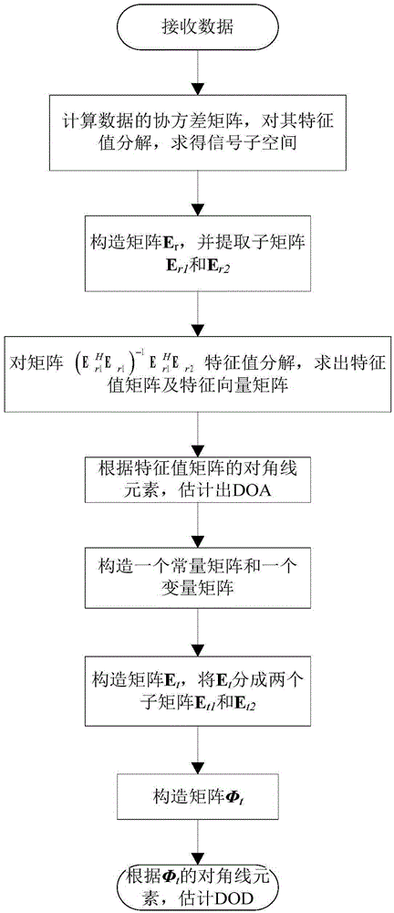
[0031] Such as figure 1 As shown, it is a flow chart for the implementation of the present invention. A method for estimating the target angle of a bistatic MIMO radar array and calibrating mutual coupling errors proposed by the present invention includes the following steps:

[0032] Step 1, the bistatic MIMO radar system at t l The data vector received at any time is:

[0033] x(t l ) = As(t l )+n(t l )(1)

[0034] In formula (1), l=1,2,...,L, L represents the snapshot number; s(t l ) means t l A P-dimensional transmit signal vector at time, n(t l ) means t l An MN-dimensional zero-mean white Gaussian noise at any moment; A represents an MN×P-dimensional array flow pattern matrix, where M represents the number of array elements in the transmitting array, N represents the number of array elements in the receiving array, and P represen...


PUM


Abstract

The invention discloses a bistatic MIMO radar array target angle estimation and mutual coupling error calibration method. The method comprises the following steps: 1, data received by the bistatic MIMO radar system at tl time are x(tl); 2, a covariance matrix R for received data vectors x(tl) is calculated, a feature value of the R is decomposed, and a signal sub space matrix Es is obtained; 3, a matrix Er is built, and sub matrixes Er1 and Er2 are extracted; 4, a feature value of a matrix as described in the specifications is decomposed, and a feature value matrix phir and a feature vector matrix Q are obtained; 5, according to diagonal line elements of the matrix phir, a DOA is estimated; 6, a constant matrix Ft and a transformation matrix B are built; 7, according to the constant matrix Ft, the transformation matrix B and the matrix Es in the second step, a matrix Et is built, and sub matrixes Et1 and Et2 for the Et are extracted; 8, by using the Q in the fourth step and the Et1 and the Et2 in the seventh step, a matrix phit is built; and 9, according to the diagonal line elements of the matrix phit, a DOD is estimated. Spectral peak search does not need to be carried out on the angle, the estimation precision is high, and good estimation performance can be obtained even in a low signal-to-noise ratio environment.

Description

technical field [0001] The invention belongs to the field of radar signal processing, and relates to angle estimation and error calibration of bistatic multi-input multi-output (MIMO) radar signals, in particular to a method for bistatic MIMO radar system target angle estimation and error calibration. A method for mutual coupling error calibration. Background technique [0002] In recent decades, target angle estimation has been an important research content in the field of radar signal processing. The direction of departure (Direction of Departure, DOD) and reception angle ( Direction of Arrival (DOA) estimation, its resolution is obviously better than traditional phased array radar. For the estimation of DOD and DOA of bistatic MIMO radar signals, a large number of effective methods have been proposed and some important progress has been made. However, the existing methods do not consider the mutual coupling effect between the elements of the bistatic MIMO radar array. ...

Claims


Application Information

Patent Timeline
Patent Type & Authority Applications(China)
IPC IPC(8): G01S7/41G01S7/40G01S13/00
CPCG01S7/40G01S7/41G01S13/003
Inventor 戴继生汪洋李琳邹航鲍煦
Owner JIANGSU UNIV
Why Eureka
Try Eureka