Power grid voltage regulation method of angle form cascade synchronous compensator

A cascading synchronization and grid voltage technology, applied in the direction of AC network voltage adjustment, reactive power compensation, reactive power adjustment/elimination/compensation, etc., can solve the problem that reactive power compensation devices cannot meet the application requirements, affect the efficiency of new energy generation, Problems such as large voltage deviation

Active Publication Date: 2016-03-16
HUNAN UNIV
View PDF2 Cites 14 Cited by
  • Summary
  • Abstract
  • Description
  • Claims
  • Application Information

AI Technical Summary

Problems solved by technology

[0002] With the continuous development of the electric power industry, the requirements of the power grid for reactive power supply are becoming increasingly stringent, and the traditional reactive power compensation device has been difficult to meet the application requirements of some special occasions
Renewable energy sources such as photovoltaics and wind power are often affected by the natural environment, and have the characteristics of intermittent, random and uncertain, and their output power will fluctuate, resulting in unqualified grid-connected power factor, large voltage deviation, and voltage fluctuations and flicker, which affect the power generation efficiency of new energy, and may cause large-scale disconnection of power plants in severe cases

Method used


Image

  • Power grid voltage regulation method of angle form cascade synchronous compensator
  • Power grid voltage regulation method of angle form cascade synchronous compensator
  • Power grid voltage regulation method of angle form cascade synchronous compensator

Examples


Embodiment Construction

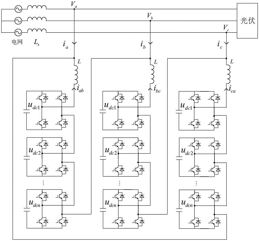
[0031] see figure 1 , is the topological structure diagram of an angular cascaded synchronous compensator (STATCOM) cascaded with n H-bridge modules for each phase, where V a , V b , V c is the voltage of the common connection point of the three-phase grid, L s is the grid equivalent reactance, i a i b i c is the angular cascaded STATCOM line current, L is the angular cascaded STATCOM filter reactance, i ab ibc i ca is the angular cascade STATCOM phase current, U dc1 , U dc2 ... U dcn is the DC side voltage of each sub-module. When the power grid voltage is unbalanced, flickering or contains more harmonic components, there may be errors in the frequency and phase information extracted by the traditional phase-locked loop. Therefore, the voltage detection based on the generalized second-order integrator is used to quickly and accurately Extract phase and frequency information, so that the system can still ensure accurate grid synchronization under asymmetrical faults...


PUM


Abstract

The invention discloses a power grid voltage regulation method of an angle form cascade synchronous compensator. Unbalanced three-phase power grid voltage is independently subjected to positive and negative sequence voltage detection to obtain positive sequence voltage dq shaft components Vd[P] and Vq[P] and negative sequence voltage dq shaft components Vd[N] and Vq[N]; a difference value between the positive sequence voltage dq shaft components and a voltage control instruction as well as a difference between the negative sequence voltage dq shaft components and the voltage control instruction can be independently obtained, and a deviation is subjected to slip form PI control to obtain a STATCOM (Satellite Communications) line current positive and negative sequence dq shaft control instruction; after the STATCOM line current positive and negative sequence dq shaft control instruction is subjected to synchronous frame transform, zero sequence circulating current is combined to obtain a STATCOM phase current instruction; the STATCOM phase current instruction is subjected to current dead-beat control to obtain each-phase chain link modulating wave signal; carrier phase-shifting modulation is used for controlling each module switch to act, finally, positive sequence reactive current and negative sequence current are injected into a power grid, the positive sequence voltage of the power grid is supported, and the voltage fluctuation of a point of common coupling is reduced; and the negative sequence voltage of the point of common coupling is inhibited, and the unbalance of power grid voltage is improved. A slip form PI control method adopted by the invention can quickly support the positive sequence voltage of the power grid, control the positive sequence voltage of the power grid, inhibit short-time voltage leap and maintain the stability of the power grid voltage.

Description

technical field [0001] The invention relates to a voltage support strategy of a static synchronous compensator, in particular to a grid voltage regulation method of an angular cascaded synchronous compensator (STATCOM). Background technique [0002] With the continuous development of the electric power industry, the requirements of the power grid for reactive power supply are becoming increasingly strict, and the traditional reactive power compensation device has been difficult to meet the application requirements of some special occasions. Renewable energy sources such as photovoltaics and wind power are often affected by the natural environment, and have the characteristics of intermittent, randomness and uncertainty. Their output power will fluctuate, resulting in unqualified grid-connected power factors, large voltage deviations, and voltage fluctuations and flicker, which affect the power generation efficiency of new energy sources, and may cause large-scale disconnecti...

Claims


Application Information

Patent Timeline
Patent Type & Authority Applications(China)
IPC IPC(8): H02J3/16H02J3/18
CPCH02J3/16H02J3/1857Y02E40/30
Inventor 罗安黄旭程何志兴孟浩岳雨霏
Owner HUNAN UNIV
Why Eureka
Try Eureka