High-speed printed circuit board and difference wiring method therefor

A high-speed printing, differential line technology, applied in the directions of printed circuits, printed circuits, printed circuit manufacturing, etc., can solve problems such as the inability to meet high-speed signal quality requirements

Active Publication Date: 2016-03-16
GUANGZHOU FASTPRINT CIRCUIT TECH +2
View PDF4 Cites 6 Cited by
  • Summary
  • Abstract
  • Description
  • Claims
  • Application Information

AI Technical Summary

Problems solved by technology

Traditional printed circuit board layout methods will not be able to meet high-speed signal quality requirements

Method used


Image

  • High-speed printed circuit board and difference wiring method therefor
  • High-speed printed circuit board and difference wiring method therefor
  • High-speed printed circuit board and difference wiring method therefor

Examples


Embodiment Construction

[0038] Embodiments of the present invention are described in detail below:

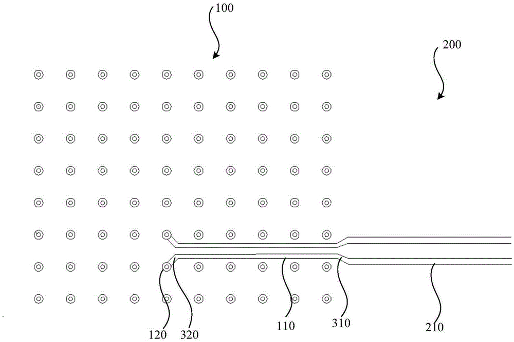
[0039] Such as figure 1 As shown, a high-speed printed circuit board at least includes sequentially stacked wiring layers, dielectric layers (not identified in the drawings) and shielding layers (not identified in the drawings). The wiring layer includes a BGA area 100 , a non-BGA area 200 and two differential transmission lines oppositely arranged. The two differential transmission lines both include a first differential line 110 located in the BGA area 100, a second differential line 210 located in the non-BGA area 200, and a first connection line 310 connecting the first differential line 110 and the second differential line 210 . The width of the first differential line 110 is smaller than the width of the second differential line 210 , and the distance between the two first differential lines 110 is smaller than the distance between the two second differential lines 210 . The width of the firs...


PUM


Abstract

The invention discloses a difference wiring method for a high-speed printed circuit board. The difference wiring method comprises the following steps: setting a preset impendence required value in a non-BGA region to be Z2, and determining a second difference line width w2 and a distance d2 between the second difference lines according to the preset impendence required value Z2; calculating a first difference line width w1 and a distance d1 between the first difference lines according to a distance s1 between adjacent two lines of bonding pads in a BAG region bonding pad array, and a minimum processing distance s2 from the bonding pad to the first difference lines, wherein w1 and d1 satisfy the inequation that the 2w1+d1 is less than or equal to s1-2s2; meanwhile, further calculating the w1 and d1 according to a difference characteristic impendence formula; arranging two first difference lines that are arranged in opposite in the BGA region according to the determined d1; arranging two second difference lines that are arranged in opposite in the non-BGA region according to the determined d2; connecting the first difference lines and the corresponding second difference lines through a first connecting line; and connecting the first difference lines and the corresponding first bonding pads through a second connecting line.

Description

technical field [0001] The invention relates to the technical field of circuits, in particular to a high-speed printed circuit board and a differential wiring method thereof. Background technique [0002] The printed circuit board includes at least a wiring layer, a shielding layer and a dielectric layer, and the wiring layer includes a signal line, a BGA (BallGridAssay, solder ball array package) area, and a non-BGA area. There are a large number of differential wiring methods for PCB boards. Generally, the wiring width should be controlled within a reasonable wiring width in the non-BGA area, and the line width / distance is relatively large; while the distance between the pin arrays in the BGA area is relatively small, designers generally use non-BGA wiring. The line width of the differential pair in the BGA area is the same, and the distance between the differential pair is reduced and arranged in the BGA area to interconnect with the non-BGA area. In fact, the above desi...

Claims


Application Information

Patent Timeline
Patent Type & Authority Applications(China)
IPC IPC(8): H05K1/02H05K1/11
CPCH05K1/0245H05K1/025H05K1/11H05K2201/10734H05K2201/09236H05K2201/09727H05K1/111H05K1/02H01L23/49816H01L23/49822H05K1/115H05K1/117H05K3/4038
Inventor 范红王红飞陈蓓
Owner GUANGZHOU FASTPRINT CIRCUIT TECH
Why Eureka
Try Eureka