Defoaming reaction vessel

A reaction kettle and kettle body technology, applied in chemical/physical/physical-chemical stationary reactors, foam dispersion/prevention, degassing by vibrating liquid, etc., can solve the problems of air pressure change, reduced foam removal effect, and high cost, To achieve the effect of reasonable stroke, exquisite structure and elimination of air bubbles

Inactive Publication Date: 2016-03-23
盐城盛大肠衣食品有限公司
View PDF6 Cites 6 Cited by
  • Summary
  • Abstract
  • Description
  • Claims
  • Application Information

AI Technical Summary

Problems solved by technology

[0002] Reactor, a device used to mix and stir raw materials in a sealed state. The reactor is composed of a kettle body, a kettle cover, a jacket, a stirrer, a transmission device, a shaft seal device, a support, etc.; it has good acid resistance, Alkali resistance, effective impact resistance, and can provide a certain pressure environment; in the actual use process, many reactions are often accompanied by foam, and a large amount of foam will also be generated when stirring some slurries. A defoamer is added inside, but this method will introduce impurities to the reactants and reduce the purity of the raw materials; in order to avoid this phenomenon, some reactors are equipped with screens in the cavity, but the screens are soaked by the reactants. The defoaming effect is greatly reduced, so the defoaming effect is not obvious after a period of use; in addition, when using the reactor for physical and chemical reactions, the temperature, pressure, mechanical control and other conditions of the reactor need to be controlled within a more precise range inside; part of the reactor has air guide holes inside to blow out the bubbles through the airflow, but this will cause the air pressure in the reactor to change, so it cannot be widely promoted in actual use; at the same time, the above-mentioned defoaming device also has complex structures, high cost defects

Method used


Image

  • Defoaming reaction vessel
  • Defoaming reaction vessel
  • Defoaming reaction vessel

Examples


Embodiment 1

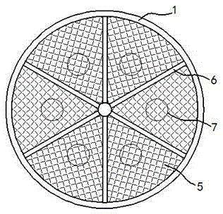
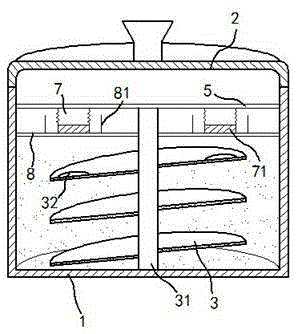
[0018] exist figure 1 , figure 2 In the shown embodiment one, this defoaming reaction kettle includes a kettle body 1, a kettle cover 2 and a rotating shaft 31, and a threaded paddle 3 for stirring is also installed on the rotating shaft 31; Permanent magnet blocks 32 are installed on the surface; each of the permanent magnet blocks 32 is evenly distributed on the horizontal plane relative to the rotating shaft 31 circumferentially; The bottom surface of the body 1 is parallel; the defoaming device includes a limit screen 5 and a support 6, and the limit screen 5 is installed on the rotating shaft 31; the support 6 is fixed on the limit screen 5 Below; the support 6 divides the limiting screen 5 into 6 fan-shaped areas; in each of the fan-shaped areas, elastic airbags 7 are also distributed on the lower surface of the limiting screen 5, and each The side wall of the elastic airbag 7 is provided with an air injection hole, the air injection hole is simple in structure and sm...

Embodiment 2

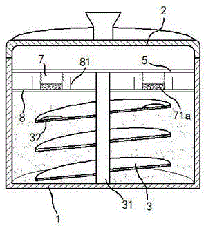
[0025] exist image 3 In the shown embodiment two, different from embodiment one, the ferromagnetic plate 71 in this embodiment is replaced by magnetic powder 71a, and the particle size of the magnetic powder 71a is larger than the size of the gas injection hole; when the permanent magnet block When 32 is close to the magnetic powder 71a and absorbs the magnetic powder 71a, the elastic airbag 7 stretches and sucks the surrounding gas and air bubbles. At this time, the magnetic powder 71a is concentrated at the bottom of the elastic airbag 7; Return to the original shape and bounce back, the internal gas is sprayed out along each of the gas injection holes, and the magnetic powder 71a at the bottom is bounced and scattered in the elastic airbag 7 at the same time, and the bubbles in the elastic airbag 7 are quickly broken; compared with Embodiment 1 , the present embodiment strengthens the defoaming effect inside the elastic airbag 7, and further improves the defoaming effect; ...


PUM


Abstract

The invention relates to a defoaming reaction vessel. The defoaming reaction vessel comprises a vessel body, a vessel cover and a rotating shaft. Thread paddles used for stirring are installed on the rotating shaft. A permanent magnetism block is installed on the upper surface of each thread paddle. A defoaming device is installed in the vessel body. The defoaming device comprises a spacing screen plate and a support. The support is fixed under the spacing screen plate. Elastic air bags are distributed on the lower surface of the spacing screen plate. A blowhole is arranged in the side wall of each elastic air bag. A ferromagnetic plate is installed at the bottom of each elastic air bag. A defoaming screen plate is fixedly installed on each ferromagnetic plate. Each defoaming screen plate can slide up and down along the side wall of the support. The reaction vessel is delicate in structure, is low in cost and can achieve high-efficiency defoaming on the premise of constant voltage, new impurities cannot be introduced, and high-efficiency and stable operation of the reaction is ensured.

Description

technical field [0001] The invention relates to a chemical equipment, in particular to a reaction kettle. Background technique [0002] Reactor, a device used to mix and stir raw materials in a sealed state. The reactor is composed of a kettle body, a kettle cover, a jacket, a stirrer, a transmission device, a shaft seal device, a support, etc.; it has good acid resistance, Alkali resistance, effective impact resistance, and can provide a certain pressure environment; in the actual use process, many reactions are often accompanied by foam, and a large amount of foam will also be generated when stirring some slurries. A defoamer is added inside, but this method will introduce impurities to the reactants and reduce the purity of the raw materials; in order to avoid this phenomenon, some reactors are equipped with screens in the cavity, but the screens are soaked by the reactants. The defoaming effect is greatly reduced, so the defoaming effect is not obvious after a period of...

Claims


Application Information

Patent Timeline
Patent Type & Authority Applications(China)
IPC IPC(8): B01J19/20B01D19/02
CPCB01D19/0078B01D19/02B01J19/20
Inventor 金伟强
Owner 盐城盛大肠衣食品有限公司
Why Eureka
Try Eureka