Acoustic material cutting device

A cutting device and acoustic material technology, applied in sampling devices, metal processing, etc., can solve the problems of uneven cutting, complex device structure, low cutting efficiency, etc., and achieve the effect of reducing cutting time, ensuring flexibility, and smooth edges

Inactive Publication Date: 2016-03-23
JILIN UNIV
View PDF7 Cites 15 Cited by
  • Summary
  • Abstract
  • Description
  • Claims
  • Application Information

AI Technical Summary

Problems solved by technology

The device described in this patent can accurately and conveniently cut out acoustic material samples of predetermined specifications, but the device has the disadvantage of low cutting efficiency; Acoustic material sample cutting machine" (Patent No. 201510232747.4)
The device described in this patent uses two different methods of motor drive and manual rotation to cut materials, and the cutting efficiency has been improved. At that time, there were shortcomings of uneven cutting and low cutting safety performance; the Chinese patent publication number is CN203672650U, and the publication date is 2014 On June 25, 2014, the name of the invention was "Electric Sampling Tool for Acoustic Materials" (Patent No. 201420021813.4)
The cutting device described in the patent is driven by a motor, and two different types of cutting blade devices are hung on the beam to cut materials of different sizes at the same time, and the cutting efficiency is improved, but the structure of the device is complicated and the cost is high

Method used


Image

  • Acoustic material cutting device
  • Acoustic material cutting device
  • Acoustic material cutting device

Examples


Embodiment Construction

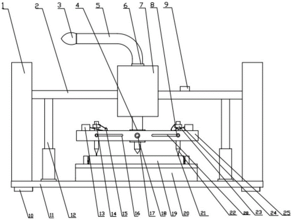
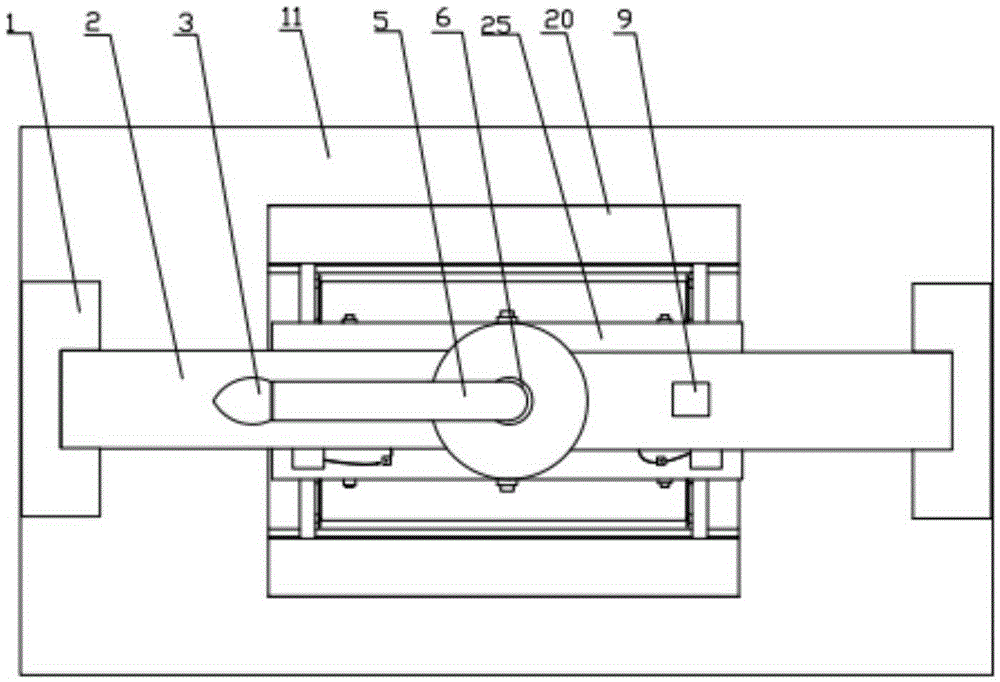
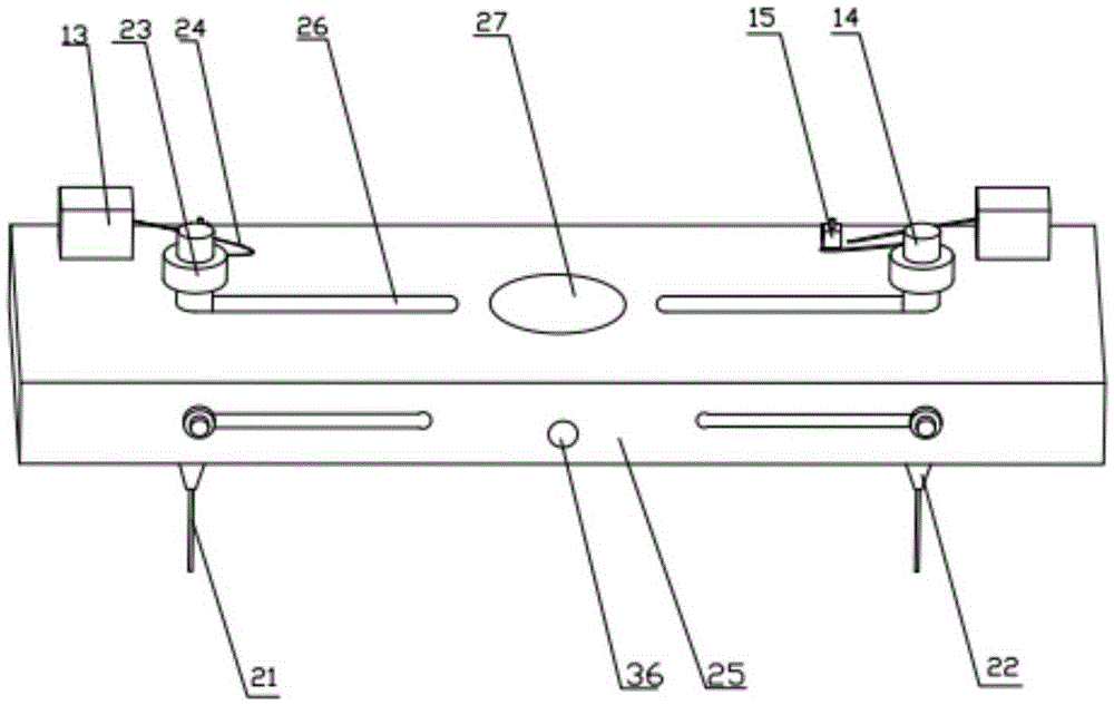
[0030] refer to figure 1 , figure 2, an acoustic material cutting device, the device includes a manual rotating device, a cutting device part, a material clamping device 20, a support device and a hydraulic jack device 12; wherein said manual rotating device is fixed on the cutting device part; said The material clamping device 20 is fixed at the middle position of the support device; the hydraulic jack device 12 is arranged at both ends of the material clamping device 20 and fixed on the support device; the cutting device part is arranged at the lower end of the manual rotation device, And the cutting head in the part of the cutting device before the test is in contact with the upper surface of the acoustic material clamped by the material clamping device, and will move up and down with the hydraulic jack during the test.

[0031] refer to figure 1 , figure 2 , the manual rotating device includes crank handle 3, drill rod 5, bearing 6, drill pipe 7 and laser light 18; wh...


PUM

PropertyMeasurementUnit
diameteraaaaaaaaaa

Abstract

The invention relates to a material cutting device, in particular to an acoustic material cutting device which comprises a manual rotating device, a cutting device part, a material clamping device, a supporting device and two hydraulic jack devices, wherein the manual rotating device is fixed to the cutting device part; the material clamping device is fixed to the middle position of the supporting device; the hydraulic jack devices are arranged at the two ends of the material clamping device and are fixed to the supporting device; the cutting device part is arranged at the lower end of the manual rotating device; a cutting head in the cutting device part is in contact with the upper surface of an acoustic material clamped by the material clamping device, and can move up and down along with the movement of the hydraulic jack devices. The acoustic material cutting device adopts an electric heating method to cut a material, so that the material cutting efficiency is high, height and cutting speed of the cutting speed can be manually controlled, cutting flexibility is guaranteed, and the material cutting time can be greatly reduced.

Description

technical field [0001] The invention relates to a material cutting device, in particular to an acoustic material cutting device. Background technique [0002] In the field of acoustic packaging design and noise control of automotive vibration and noise, it is necessary to know the acoustic properties of various materials in order to select the acoustic materials required for automotive acoustic packaging design and noise control to effectively control automotive noise. This requires the use of the standing wave tube method to measure the performance of various acoustic materials. When the standing wave tube method is used to test the performance of acoustic materials, the standing wave tube has strict requirements on the shape and size of the tested sample. However, different standing wave tube test systems have different requirements for the diameter of the sample. Traditionally, in order to obtain the standard sample required for the test, a cutting device that can change ...

Claims


Application Information

Patent Timeline
Patent Type & Authority Applications(China)
IPC IPC(8): B26F3/08B26D7/02B26D5/10B26D7/26B26D1/43G01N1/04
CPCB26D1/43B26D5/10B26D7/025B26D7/2628B26F3/08G01N1/04
Inventor 陈书明张继修王登峰陈静郭晗井晓瑞王连会姜洋
Owner JILIN UNIV
Why Eureka
Try Eureka