
Blown film cooling method and device based on air source dynamic distribution

A technology of dynamic distribution and blown film, which is applied in the field of blown film cooling, can solve the problems of uneven film thickness, poor film transparency, uneven air outlet, etc., achieve flexible and convenient application, improve film quality, and simple device principle Effect

Active Publication Date: 2016-03-23
SOUTH CHINA UNIV OF TECH +2
View PDF5 Cites 3 Cited by
  • Summary
  • Abstract
  • Description
  • Claims
  • Application Information

AI Technical Summary

Problems solved by technology

Its disadvantages are that the wind is uneven and the cooling effect is poor, resulting in uneven film thickness and poor film transparency.
[0005] In view of the problems of uneven air outlet, poor cooling effect and complex structure in the current cooling air ring, it is of great significance to develop a new blown film cooling method and device.

Method used


Image

  • Blown film cooling method and device based on air source dynamic distribution

Examples


Embodiment 1

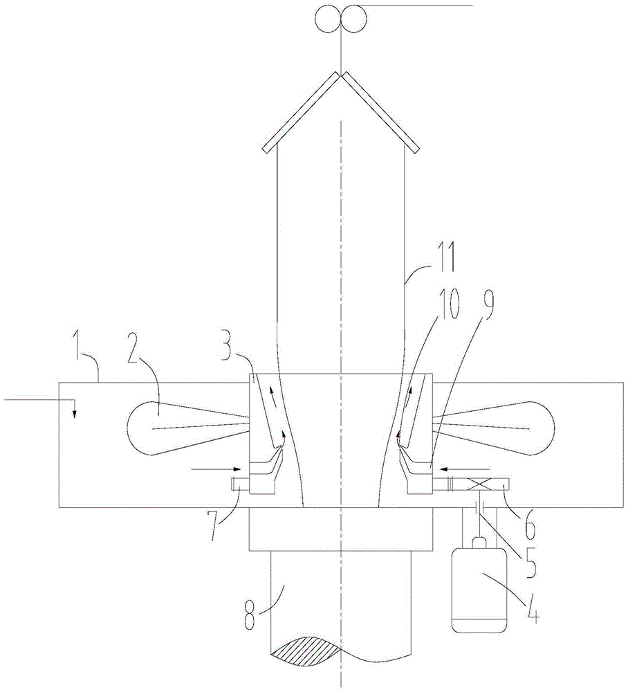
[0026] In this embodiment, a blown film cooling device based on the dynamic distribution of air sources includes an air ring body assembly and a drive assembly, such as figure 1 As shown, the blown film cooling device based on the dynamic distribution of air source is placed above the die head 8. The air ring body assembly includes the outer ring 1 of the air ring, the distribution fan 2, and the outer ring 3 of the air outlet. The drive assembly includes the drive motor 4, Power output shaft 5, driving gear 6 and driven gear 7. The driven gear is connected with the distribution fan, the driving motor drives the driving gear to rotate through the power output shaft, and the driving gear meshes with the driven gear to drive the distribution fan to rotate.

[0027] In the air ring body assembly, the air inlet 9 is arranged on the outer wall of the outer ring of the air outlet, the air outlet 10 is arranged on the inner wall of the outer ring of the air outlet, and several throug...

Embodiment 2

[0035] In this embodiment, a blown film cooling method based on the dynamic distribution of air source is realized through the device described in Embodiment 1. The rotation of the distribution fan is used to generate negative pressure, and the cold air is sucked into the annular air cavity, and due to the rotation of the distribution fan , the cold air forms a cooling airflow evenly distributed in the circumferential direction at the annular air outlet, and the cooling airflow blows to the surface of the film bubble, and the cooling airflow is evenly distributed from the air source to cool the film bubble evenly. Wherein, the cooling airflow at the cooling air ring is a rotating annular airflow, and the annular airflow blows towards the outer surface of the film bubble.


PUM


Abstract

The invention discloses a blown film cooling method and device based on air source dynamic distribution. The method comprises the steps that negative pressure is generated through rotation of a distribution fan, cold air is sucked into an annular air cavity, the cold air forms cooling airflow evenly distributed in the circumferential direction at the annular air outlet, the cooling airflow is blown to the surface of a film bubble, and the cooling airflow is evenly distributed from an air source to evenly cool the film bubble. The device comprises an air ring body assembly and a drive assembly. The air ring body assembly comprises air ring outer rings, the distribution fan and an air outlet outer ring, the distribution fan is arranged on the outer side wall of the air outlet outer ring, the air ring outer rings are arranged on the peripheries of the distribution fan and the air outlet outer ring, and the drive assembly drives the air outlet outer ring to drive the distribution fan to rotate. The blown film cooling device can directly replace an air blower and a cooling air ring in traditional equipment, the air blower and the cooling air ring are combined into one, and therefore the size of equipment is reduced, and the cost is effectively reduced.

Description

technical field [0001] The invention relates to the technical field of cooling for molding and processing of polymer materials, in particular to a method and device for blown film cooling based on dynamic distribution of air source. Background technique [0002] In the plastic film blowing process, the air ring is an indispensable basic component for the formation and cooling of the bubbles in the blow molding process. The uniformity of cooling will have a great impact on the thickness, transparency, surface gloss and physical and mechanical properties of the film. [0003] In the production of extrusion blown film, the traditional external air ring adopts the direct blowing method, and the cold air is blown into the external air ring of the die head of the film blowing machine by a cooling fan to externally cool the film bubble. Its disadvantages are that the wind is uneven and the cooling effect is poor, which leads to uneven film thickness and poor film transparency. In...

Claims


Application Information

Patent Timeline
Patent Type & Authority Applications(China)
IPC IPC(8): B29C35/16B29C55/28
CPCB29C35/16B29C55/28B29C2035/1658
Inventor 瞿金平
Owner SOUTH CHINA UNIV OF TECH
Learn More