Ultrasonic vibration micro-foaming injection molding device and method for plastic inspection well

A plastic inspection well and ultrasonic vibration technology, applied in the direction of coating, etc., can solve the problems of low foaming efficiency, large consumption of plastic raw materials, low product strength, etc., and achieve the effect of enhancing mechanical strength, improving mechanical strength, and eliminating weld lines

Active Publication Date: 2017-07-11
江苏正林环保科技有限公司
View PDF12 Cites 0 Cited by
  • Summary
  • Abstract
  • Description
  • Claims
  • Application Information

AI Technical Summary

Problems solved by technology

The mass of plastic inspection wells is usually dozens of kilograms or even hundreds of kilograms, with complex shapes and large sizes. Large-scale plastic inspection wells generally adopt traditional injection molding methods, and traditional injection molding requires high speed and high pressure to meet the rapid filling of large-flow plastic melts. Mold cavity, therefore, plastic inspection wells have always had problems in conventional injection molding: large consumption of plastic raw materials, high energy consumption, complex process and difficulty in molding quality control
[0004] In recent years, foam injection molding is a new direction of plastic molding processing. Foam injection molding has the advantages of good dimensional accuracy and low material consumption. Domestic and foreign scientific research workers and technicians have carried out a lot of research on foam injection molding equipment and processes. Innovative research and application, for example, Patent No.: 201010595524.1 discloses a method for preparing thermoplastic micro-foaming injection molding pipe fittings with a supercritical fluid control system, but this foaming injection molding requires a complex supercritical fluid control system; Patent No.: 200710026663.0 discloses a chemical foaming high-speed injection molding method using a pre-compression method. Although this chemical method is simple to foam, the size of the foamed cavity is not easy to control, and the product strength is low; Patent Application No. 201110356065.6 uses polymer Composite materials, by adding foaming agents, foaming aids and other materials to the plastic raw materials, this is to generate foaming during the screw shear plasticization process and complete injection molding, and the foaming efficiency is low
At present, foam injection molding has been widely used in plastic products in various engineering fields, but each has its own scope of application and limitation of conditions. Due to the special molding process of plastic inspection wells, foam injection molding has not yet been applied to injection molding of large plastic inspection wells. forming

Method used


Image

  • Ultrasonic vibration micro-foaming injection molding device and method for plastic inspection well
  • Ultrasonic vibration micro-foaming injection molding device and method for plastic inspection well
  • Ultrasonic vibration micro-foaming injection molding device and method for plastic inspection well

Examples


Embodiment 1

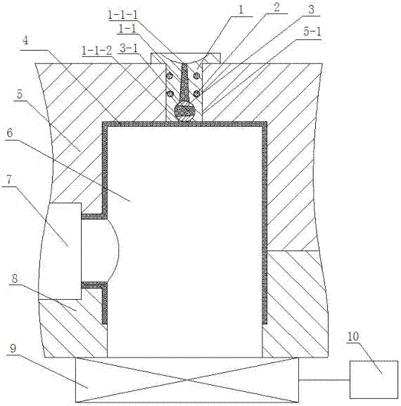
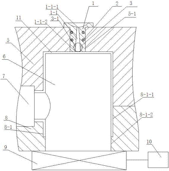
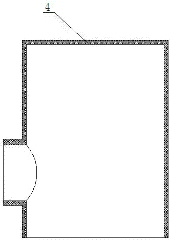
[0037] Embodiment 1: see attached figure 1 ~ attached Figure 5 , an ultrasonic vibration micro-foaming injection molding device for a plastic inspection well, comprising a fixed template 5, a movable template 8, a mold core and a hot runner system, an ultrasonic vibration device 9, and a control system 10, and the mold core includes a mold main core 6 , side-drawn core 7, the mold core is located between the fixed template 5 and the movable template 8, the side-drawn core 7 is adjacent to the main mold core 6 of the mold, and a mold core is provided between the fixed template 5 and the movable template 8 The mold cavity 11, the hot runner system is arranged on the fixed template 5, and the fixed template 5 is provided with a through cavity 5-1, and the hot runner system includes a sprue sleeve 1 embedded in the through cavity 5-1 of the fixed template 5, The heater 2 arranged on the outer edge of the sprue bushing 1, the sprue 1-1, the rotatable steering switch 3 arranged on...

Embodiment 2

[0052] Embodiment 2: see attached figure 1 ~ attached Figure 5 , a plastic inspection well ultrasonic vibration micro-foaming injection molding device, the matching gap between the arc-shaped protrusion 7-1 of the side-drawing core 7 and the arc-shaped groove 6-1 of the main mold core 6 in this embodiment is 0.05mm; The lower end clearance of the mold main core 6 is matched with the second through hole 8-1-2 of the stepped through hole 8-1 on the movable template 8, and the matching clearance is 0.03mm; the steering switch 3 is a cylinder valve. All the other structures are the same as in Example 1.

[0053] The injection molding method using the ultrasonic vibration micro-foaming injection molding device for plastic inspection wells includes two stages of injection molding and micro-foaming. The first is injection molding. The injection molding includes the following steps:

[0054] (1) First, prepare before injection molding and plasticize the injection molding machine. A...


PUM

PropertyMeasurementUnit
diameteraaaaaaaaaa
diameteraaaaaaaaaa
diameteraaaaaaaaaa

Abstract

The invention relates to an ultrasonic vibration micro-foaming injection moulding device and an ultrasonic vibration micro-foaming injection moulding method for a plastic inspection well, and relates to the field of injection moulding machining for plastic inspection wells. The ultrasonic vibration micro-foaming injection moulding device comprises a fixed die plate, a movable die plate, a die core and hot runner system, an ultrasonic vibration device and a control system, wherein die cores comprise a main die core and a side pulling core, and a die cavity is arranged among the die cores, the fixed die plate and the movable die plate. According to the invention, a cavitation foaming effect of ultrasonic vibration on plastic is utilized, the die cavity is filled with a plastic melt through injection moulding to reach 85-90% of the volume of the die cavity at first, and then the plastic melt in the die cavity is subjected to overall ultrasonic vibration and cavitation micro-foaming through the main die core provided with an ultrasonic vibration mechanism, thus micro-foaming injection moulding machining for the plastic inspection well is realized. The ultrasonic vibration micro-foaming injection moulding device disclosed by the invention is simple to operate, high in moulding accuracy, and capable of saving plastic raw materials by 10-15%, reducing an injection moulding pressure by 60-80%, saving energy, avoiding or reducing generation of weld marks, enhancing the product strength and prolonging the service life.

Description

technical field [0001] The invention relates to the field of injection molding processing of plastic parts, in particular to an ultrasonic vibration micro-foaming injection molding device for a plastic inspection well and a method thereof. Background technique [0002] Plastic inspection well is an important part of municipal pipe network construction. It is a green and environmentally friendly product with high social and economic value. In recent years, the demand in domestic and foreign markets has been increasing, and the development prospect is broad. The mass of plastic inspection wells is usually dozens of kilograms or even hundreds of kilograms, with complex shapes and large sizes. Large-scale plastic inspection wells generally adopt traditional injection molding methods, and traditional injection molding requires high speed and high pressure to meet the rapid filling of large-flow plastic melts. Mold cavity, therefore, there are always problems in conventional injec...

Claims


Application Information

Patent Timeline
Patent Type & Authority Patents(China)
IPC IPC(8): B29C45/00B29C45/17
CPCB29C45/0046B29C45/0053B29C2045/0039
Inventor 谭文胜刘庆新杨桂府徐波李洪达王桂林
Owner 江苏正林环保科技有限公司
Why Eureka
Try Eureka