Separate injection well immovable tubular column mechanical-electrical integration scale removing system and method

A separate injection well, electromechanical technology, applied in the direction of drilling pipe, casing, cleaning equipment, etc., can solve the problems of measurement and adjustment, such as obstruction and jamming, and achieve the effect of improving the level of automation and solving the obstruction of measurement and adjustment

Active Publication Date: 2016-03-23
PETROCHINA CO LTD
View PDF6 Cites 14 Cited by
  • Summary
  • Abstract
  • Description
  • Claims
  • Application Information

AI Technical Summary

Problems solved by technology

[0005] The purpose of the present invention is to overcome problems such as resistance and jamming

Method used


Image

  • Separate injection well immovable tubular column mechanical-electrical integration scale removing system and method
  • Separate injection well immovable tubular column mechanical-electrical integration scale removing system and method
  • Separate injection well immovable tubular column mechanical-electrical integration scale removing system and method

Examples


Embodiment 1

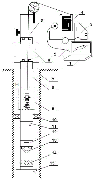
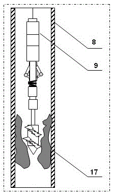
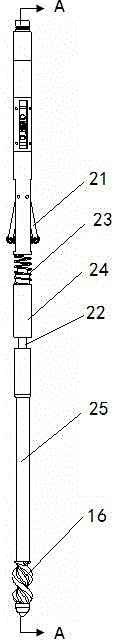
[0042] Such as figure 1 and figure 2 As shown in the figure, a mechatronic scale cleaning system for the stationary pipe string of a split injection well includes a host computer 1, which is electrically connected to a well test vehicle 3 through a signal line 2, and a cable 4 on the well test vehicle 3 is electrically connected to the electromechanical system. Descaler 9. Such as image 3 , Figure 4 and Figure 5 As shown, the electromechanical descaling instrument 9 includes a motor 18, the upper end of the motor 18 is electrically connected with the cable 4, the lower end is screwed with a reduction box 19, the lower end of the reduction box 19 is plugged with a central rod 22, and the lower end of the central rod 22 is threaded. There is a connecting rod 25, and the lower end of the connecting rod 25 is threadedly connected with a drilling mechanism 16; the outer surface of the central rod 22 is sequentially provided with a centralizing mechanism 20, an anti-reverse ...

Embodiment 2

[0049] On the basis of Example 1, such as Figure 6 , Figure 7 , Figure 8 and Figure 9 As shown, the righting mechanism 20 is composed of a righting steel body 2001, a righting upper arm 2002, and a righting lower arm 2003. The centering steel body 2001 is provided with a through hole in the axial direction to allow the center rod 22 to pass through, and a through hole for accommodating the righting upper arm is provided in the radial direction. 2002, the rectangular through hole of the righting lower arm 2003, the righting upper arm 2002 is located at one end close to the reduction box 19, the righting lower arm 2003 is located at one end close to the anti-reverse mechanism 21, and the upper end of the righting upper arm 2002 is fixed in the rectangular through hole by pins, An auxiliary pulley 2004 is provided between the lower end of the righting upper arm 2002 and the upper end of the righting lower arm 2003, the righting upper arm 2002, the righting lower arm 2003, a...

Embodiment 3

[0053] On the basis of Example 1, such as Figure 10 , Figure 11 , Figure 12 , Figure 13 and Figure 14 As shown, the anti-reverse mechanism 21 includes an anti-reverse steel body 2101, an anti-rotation arm 2103, and a thrust arm 2104. The axial direction of the anti-reverse steel body 2101 is provided with a through hole for the center rod 22 to pass through, and the radial direction A rectangular through hole is provided to accommodate the anti-rotation arm 2103 and the thrust arm 2104. The anti-rotation arm 2103 is located at one end close to the centralizing mechanism 20, the thrust arm 2104 is located at one end close to the return spring 23, and the upper end of the anti-rotation arm 2103 is fixed on the rectangular through-hole by a pin. In the through hole, double auxiliary pulleys 21052004 are arranged between the lower end of the anti-rotation arm 2103 and the upper end of the thrust arm 2104. The force arm push platform 2106 at the lower end of the rectangula...


PUM


Abstract

The invention belongs to the technical field of oil field layered water injection development technology matching processes and particularly relates to a separate injection well immovable tubular column mechanical-electrical integration scale removing system and method. According to the separate injection well immovable tubular column mechanical-electrical integration scale removing system and method, an upper computer controls an electrical and mechanical descaling instrument to be turned on and turned off, a cable-carried electrical and mechanical descaling instrument is adopted for drilling and removing dirt in a separate injection well cylinder, separate injection well penetrating and scale removing are converted to cables from steel wires and to machine electricity from machinery, the automated level of a descaling and resistance reduction technology is raised, and the problems of blocking and sticking in the measurement and regulation processes caused by wellbore scaling of the oil field separate injection well are effectively solved.

Description

technical field [0001] The invention belongs to the technical field of supporting technology for oil field layered water injection development technology, and in particular relates to a system and method for cleaning scales of a separate injection well with an electromechanical integration of a stationary pipe string. Background technique [0002] The unimpeded wellbore of separate injection wells is the basic condition to ensure normal monitoring and adjustment in the later stage. However, as the service time of the water injection string of the separate injection wells prolongs and is affected by factors such as wellbore scaling and corrosion, the logging and adjustment of the separate injection wells frequently encounters resistance, and some wells Instruments and tools fell into the well, resulting in overhaul and maintenance costs such as pressurized operations in the later stage, which affected the orderly development of layered water injection measurement and adjustmen...

Claims


Application Information

Patent Timeline
IPC IPC(8): E21B37/00E21B17/10E21B10/00
CPCE21B10/00E21B17/10E21B37/00
Inventor 王子建巨亚锋于九政杨玲智罗必林毕福伟申晓莉
Owner PETROCHINA CO LTD
Why Eureka
Try Eureka