an intake muffler
Inactive Publication Date: 2018-12-14
HUAZHONG UNIV OF SCI & TECH
View PDF8 Cites 0 Cited by
- Summary
- Abstract
- Description
- Claims
- Application Information
AI Technical Summary
Problems solved by technology
However, as the layout of the engine compartment becomes more and more compact, in the intake system with limited space, the traditional Helmtz and 1 / 4 wavelength tube intake mufflers often have disadvantages such as large number, large volume, and unsightly appearance. Restricting the NVH performance of the engine
Method used
View moreImage
Smart ImageViewing Examples

Examples
example
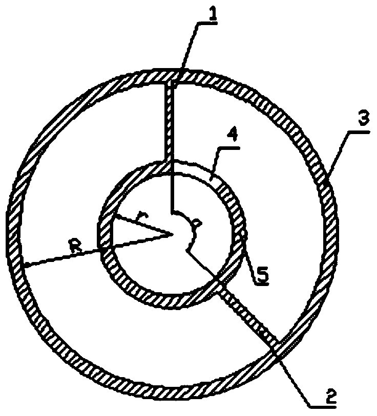
[0028] The diameter of the inlet pipe wall is about 70mm, the total length of the muffler is about 130mm, and the diameter is about 120mm. Four mufflers are connected in series inside. The engine intake muffler is applied to the intake system of a small excavator. The application results show that the intake noise of the engine can be fully reduced without affecting the engine power.
Login to View More PUM
 Abstract
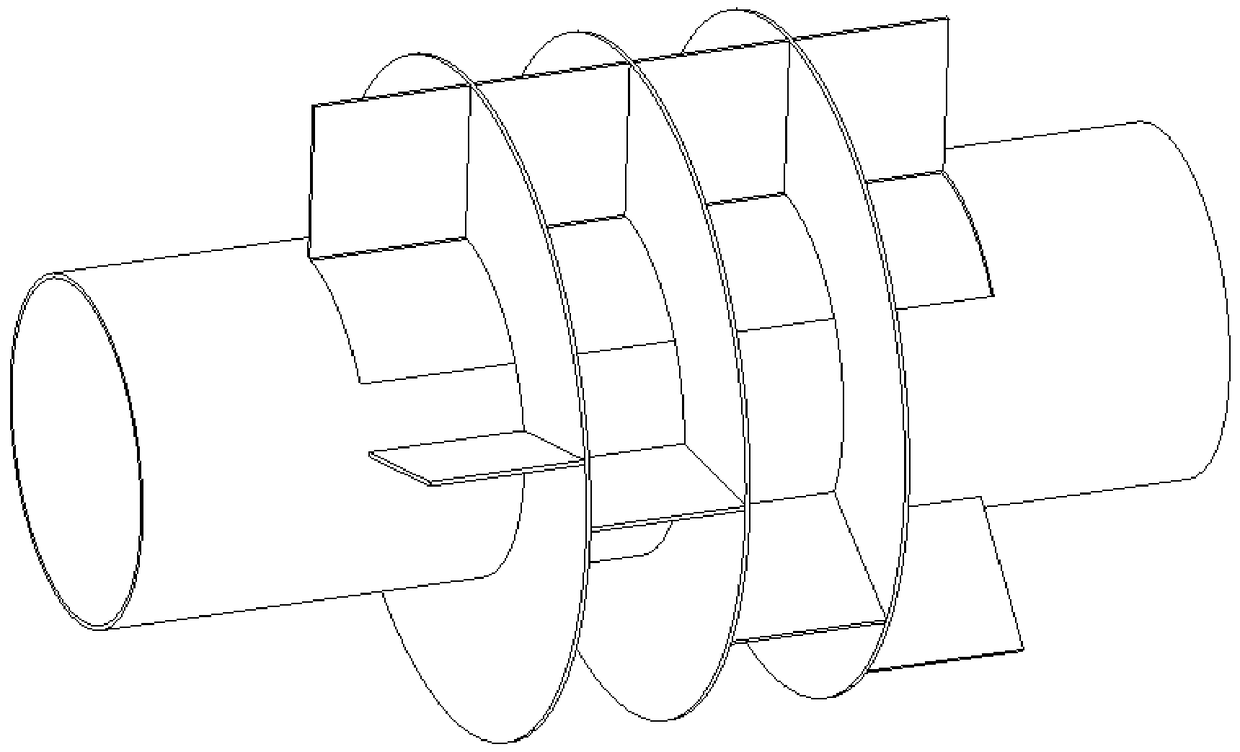
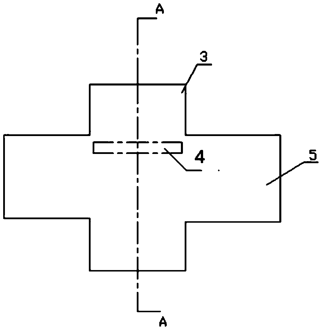
The invention discloses an air intake silencer. The air intake silencer comprises at least one annular silencing unit which is sequentially arranged in the axial direction of an air intake pipe; each silencing unit comprises an annular outer shell, a first baffle, a second baffle and a through hole formed in the wall of the air intake pipe of an engine; the surface of the air intake pipe of the engine is sleeved with the annular outer shell, the first baffle and the second baffle are installed between the annular outer shell and the air intake pipe in the radial direction, and a cavity is jointly formed by the two baffles and the annular outer shell; and the cavity is communicated with the air intake pipe of the engine through a through hole. According to the air intake silencer, the multiple silencing units are designed to be circumferentially distributed around the air intake pipe, the silencing frequency of the silencing units can be flexibly adjusted, and the target noise peak value can be eliminated; and in addition, the structure is compact, the size of the air intake silencer of the engine is reduced, and compact arrangement of all components in an engine compartment is easily achieved.
Description
technical field [0001] The invention relates to an engine intake system, in particular to an intake muffler. Background technique [0002] The industry in modern society is increasingly developed, the power of machines continues to increase, and the number of construction machinery has increased significantly. Accompanying it is that noise pollution is becoming more and more common and serious. From the perspective of the development direction of the engine industry, noise is the key technical indicator of engine product competition. In internal combustion engines, if no muffler is installed, the sound pressure level of exhaust noise is the highest, followed by intake noise. With the improvement of living standards, more and more people pay more and more attention to the problem of noise pollution. Intake noise is one of the main sound sources of engine noise, and with the increase of internal combustion engine speed and strengthening degree, the general application of turb...
Claims
Login to View More Application Information
Patent Timeline
 Patent Type & Authority Patents(China)
IPC IPC(8): F02M35/12
CPCF02M35/1244F02M35/1288
Inventor 蒋炎坤王钊轶王珺
Owner HUAZHONG UNIV OF SCI & TECH
Features
- R&D
- Intellectual Property
- Life Sciences
- Materials
- Tech Scout
- Unparalleled Data Quality
- Higher Quality Content
- 60% Fewer Hallucinations
Learn More Browse by: Latest US Patents, China's latest patents, Technical Efficacy Thesaurus, Application Domain, Technology Topic, Popular Technical Reports.
© 2025 PatSnap. All rights reserved.Legal|Privacy policy|Modern Slavery Act Transparency Statement|Sitemap|About US| Contact US: help@patsnap.com