Machine vision based light-emitting panel detection method

A light-emitting panel and machine vision technology, applied in the field of detection, can solve the problems of "fitting, poor model adaptability, poor robustness, etc., and achieve the effect of smooth and convenient processing flow, wide range of implementation, and low implementation cost

Active Publication Date: 2016-03-23
苏州富鑫林光电科技有限公司
View PDF11 Cites 17 Cited by
  • Summary
  • Abstract
  • Description
  • Claims
  • Application Information

AI Technical Summary

Problems solved by technology

The main problem of using this method for MURA defect detection is: when the MURA defect area is large and the contrast is low, when the "least squares B-spline fitting" method is used for processing, the defect features will be "fitted" into the background , but cannot achieve the purpose of "fitting"
In other words, it cannot distinguish between background and real defects
On the other hand, when the resolution of the module changes, the fitting effect...

Method used


Image

  • Machine vision based light-emitting panel detection method
  • Machine vision based light-emitting panel detection method

Examples


Embodiment Construction

[0034]The specific implementation manners of the present invention will be further described in detail below in conjunction with the accompanying drawings and embodiments. The following examples are used to illustrate the present invention, but are not intended to limit the scope of the present invention.

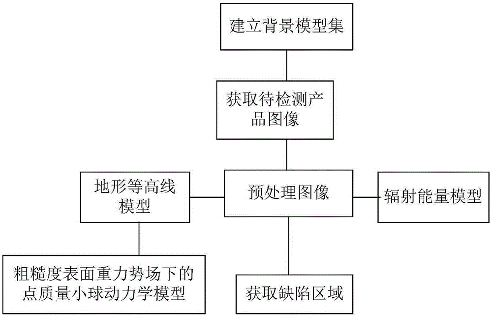
[0035] Such as figure 1 The light-emitting panel detection method based on machine vision is characterized in that it includes the following steps: first, a background model set is established. After that, the image of the product to be inspected is obtained, and the preprocessed image is obtained. Then, the preprocessed image is independently processed through the terrain contour model and radiation energy model. Finally, the previously processed data are synchronously summarized to obtain defect areas.

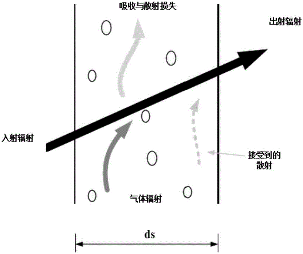
[0036] Such as figure 2 As shown, the radiant energy models involved in the present invention can be viewed from the common FLUENT software, and there are mainly fiv...


PUM


Abstract

The invention relates to a machine vision based light-emitting panel detection method. The machine vision based light-emitting panel detection method is characterized in that an image of a product to be detected is obtained by establishing a background model so as to obtain a preprocessing image; then, the image of the product is independently processed through a topographic contour model and a radiation energy model; finally, a defect region is obtained by adopting synchronously summarized processing data. Therefore, the detection requirements of various common light-emitting panels can be met. In addition, by relying on mutual matching of various models, various defects of the light-emitting panels can be effectively overcome through machine vision, and the problem of a poor MURA defect convergence effect is solved. Furthermore, the machine vision based light-emitting panel detection method can be achieved by being matched with a conventional image acquisition system, detection software and relevant mechanical mechanisms and is easy to popularize.

Description

technical field [0001] The invention relates to a detection method, in particular to a machine vision-based light-emitting panel detection method. Background technique [0002] As far as the existing technology is concerned, machine vision is to use machines instead of human eyes for measurement and judgment. Specifically, the machine vision system refers to converting the captured target into an image signal through a machine vision product (that is, an image capture device, which is divided into CMOS and CCD), and transmitting it to a dedicated image processing system to obtain the shape information of the captured target. According to information such as pixel distribution, brightness, and color, it is converted into digital signals; the image system performs various operations on these signals to extract the characteristics of the target, and then controls the on-site equipment actions according to the results of the discrimination. [0003] Specifically, taking TFT-LCD...

Claims


Application Information

Patent Timeline
IPC IPC(8): G01N21/956
CPCG01N21/956
Inventor 许照林
Owner 苏州富鑫林光电科技有限公司
Why Eureka
Try Eureka