Light source device and image display device

A light source device and light beam technology, which is applied in the field of light sources, can solve problems such as the output brightness cannot meet the brightness requirements, the transmittance and service life of optical elements are reduced, and the service life of image display devices is affected.

Inactive Publication Date: 2016-03-23
HISENSE
View PDF7 Cites 6 Cited by
  • Summary
  • Abstract
  • Description
  • Claims
  • Application Information

AI Technical Summary

Problems solved by technology

As image display devices are widely used in scenes such as cinemas, the demand for output brightness of image display devices has increased, and the output brightness (about 3000 lumens) of current image display devices cannot meet the brightness requirements; therefore, how to improve image display The output brightness of the light source of the device is a technical problem that needs to be solved urgently
[0003] In the prior art, the output brightness of the laser light source of the image display device is increased by increasing the power of the laser, thereby increasing the output brightness of the image display device; but as the output brightness of the laser light source increases, due to the thermal effect of the laser, the transmission of the optical element The efficiency and service life will continue to decrease, which will seriously affect the service life of the image display device

Method used


Image

  • Light source device and image display device
  • Light source device and image display device
  • Light source device and image display device

Examples


Embodiment 1

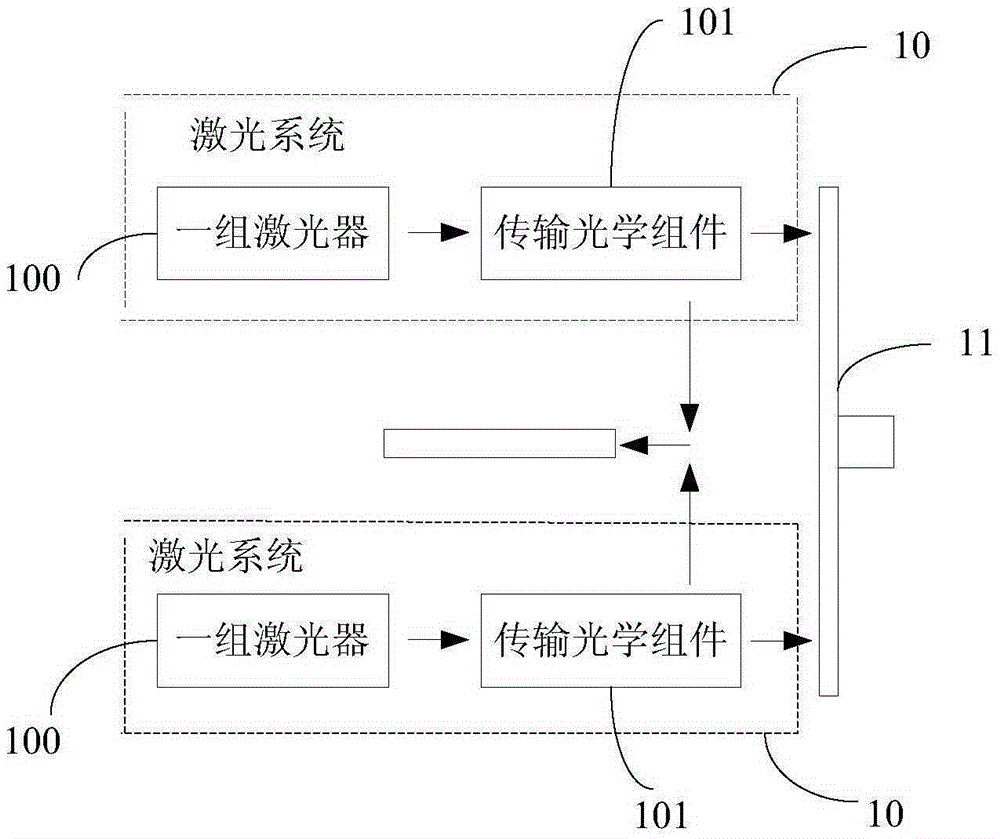
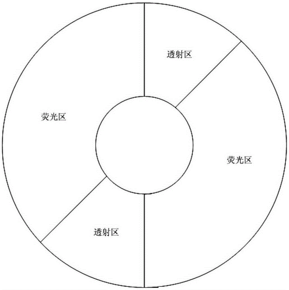
[0029] Figure 1A It is a schematic structural diagram of Embodiment 1 of the light source device of the present invention, such as Figure 1A As shown, the light source device includes: at least two groups of laser systems 10 and fluorescent wheels 11; optionally, in this embodiment, two groups of laser systems 10 are used as an example for illustration; each group of laser systems includes: a group of lasers 100 And a group of transmission optical components 101, optionally, the group of lasers can include: at least two lasers; the fluorescent wheel 11 includes: a fluorescent wheel substrate (optionally, the fluorescent wheel substrate can be a transmissive substrate Or a reflective substrate; the fluorescent wheel is rotated by a motor arranged in the center); the fluorescent wheel substrate includes: each group of corresponding fluorescent regions and transmissive regions of the laser, that is, the light source device in the embodiment of the present invention includes only ...

Embodiment 2

[0036] Figure 2A It is a structural schematic diagram of Embodiment 2 of the light source device of the present invention. On the basis of the above embodiments, the fluorescent wheel 11 is a reflective fluorescent wheel (optionally, the fluorescent wheel substrate is an aluminum plated aluminum substrate or an aluminum silver plated substrate , other parts of the fluorescent wheel substrate except the fluorescent area and the transmissive area coated with phosphor have reflection effect), each set of transmission optical components 101 includes: light-combining lens 101a (optionally, the The light-combining lens can be a dichroic mirror or other light-combining components, which is not limited in this embodiment), the first converging lens 101b, and the steering relay lens group 101c (optionally, the steering relay lens group consists of At least three first reflectors and at least three turning lenses); wherein, the light-combining lens 101a is provided with a film layer fo...

Embodiment 3

[0040] Figure 2C It is a structural schematic diagram of the third embodiment of the light source device of the present invention, in the above Figure 2A and Figure 2B On the basis of each set of transmission optical components 101 also includes: a first collimating lens group 101d and a second collimating lens group 101e; wherein, the first collimating lens group 101d is arranged on the light combining lens 101a Between the fluorescent wheel 11 ; the first collimating lens group 101d and the second collimating lens group 101e are symmetrically arranged on both sides of the fluorescent wheel substrate. Wherein, the first collimating lens group 101d is used for: collimating the first light beam passing through the light-combining lens 101a, and directing it to the fluorescent wheel 11; The divergence angle of the second light beam is large and the directionality is uncertain. The first collimating lens group 101d is also used for: collimating the second light beam reflecte...


PUM


Abstract

The embodiment of the invention provides a light source device and an image display device. The light source device comprises at least two groups of laser systems and a fluorescent wheel, wherein each group of laser systems comprises a group of laser devices and a group of transmitting optical components; the fluorescent wheel comprises a fluorescent wheel substrate; the fluorescent wheel substrate comprises fluorescent regions and transmission regions, which correspond to each group of laser devices; each fluorescent region corresponding to each group of laser devices is used for sending out at least one second light beam which is different from a first light beam in wavelength under irradiation of the first light beam generated by the laser devices; each transmission region corresponding to each group of laser devices is used for transmitting the first light beam generated by the laser devices; and each transmitting optical component is also used for merging the first light beam and the second light beam to form a mixed white light. Therefore, the output brightness of the light source device and the image display device is improved.

Description

technical field [0001] Embodiments of the present invention relate to light source technology, and in particular, to a light source device and an image display device. Background technique [0002] Usually, in image display devices (such as projectors), laser light generated by a group of lasers is mostly used as the light source of the image display device. The image generation part of the device is used to form the image to be displayed; generally, the output brightness of the light source of the image display device is about 6000-10000 lumens, and the corresponding output brightness of the image display device is about 3000 lumens. As image display devices are widely used in scenes such as cinemas, the demand for output brightness of image display devices has increased, and the output brightness (about 3000 lumens) of current image display devices cannot meet the brightness requirements; therefore, how to improve image display The output brightness of the light source of...

Claims


Application Information

Patent Timeline
Patent Type & Authority Applications(China)
IPC IPC(8): G03B21/20
CPCG03B21/204
Inventor 李巍刘显荣田有良
Owner HISENSE
Why Eureka
Try Eureka