
Direct-current electromagnetic relay drive circuit and drive method therefor

An electromagnetic relay and drive circuit technology, applied in the direction of relays, circuits, electrical components, etc., can solve the problems of slowing down the protection speed, affecting signal transmission performance, and affecting the life of the relay, so as to improve the speed of pull-in and disconnection, reduce Signal transmission delay, the effect of prolonging the life of the relay

Inactive Publication Date: 2016-03-23
BEIJING YAAO BOXIN COMM TECH CO LTD
View PDF5 Cites 4 Cited by
  • Summary
  • Abstract
  • Description
  • Claims
  • Application Information

AI Technical Summary

Problems solved by technology

[0010] (1) The delay process will make the relay contacts in a transitional state, which will cause the arcing time of the relay contacts to increase in the power circuit, increase the operating loss of the relay, and aggravate the aging of the contacts, thus affecting the life of the relay
[0011] (2) When the electromagnetic relay is used as a power switch, the pull-in delay greater than 10 milliseconds will cause power failure of the electrical equipment; if the disconnection delay is too large, the protection speed will slow down, and even cause an electrical short circuit when used in parallel
[0012] (3) When the electromagnetic relay is used for signal switching, the delay will cause the real-time performance of signal transmission to deteriorate, which will affect the signal transmission performance.

Method used


Image

  • Direct-current electromagnetic relay drive circuit and drive method therefor
  • Direct-current electromagnetic relay drive circuit and drive method therefor
  • Direct-current electromagnetic relay drive circuit and drive method therefor

Examples


Embodiment Construction

[0038] Next, preferred embodiments of the present invention will be described in detail. Examples of these preferred embodiments are illustrated in the accompanying drawings. The embodiments of the present invention shown in the drawings and described based on the drawings are merely exemplary, and the technical spirit of the present invention and its main operations are not limited to these embodiments.

[0039] Here, it should also be noted that, in order to avoid obscuring the present invention due to unnecessary details, only the structures and / or processing steps that are closely related to the solution according to the present invention are shown in the drawings, while those related to the present invention are omitted. Other details are not relevant to the invention.

[0040] The invention improves the traditional drive circuit, increases the pull-in and disconnection speed of the electromagnetic relay on the basis of adding a small amount of low-cost components, prolo...


PUM


Abstract

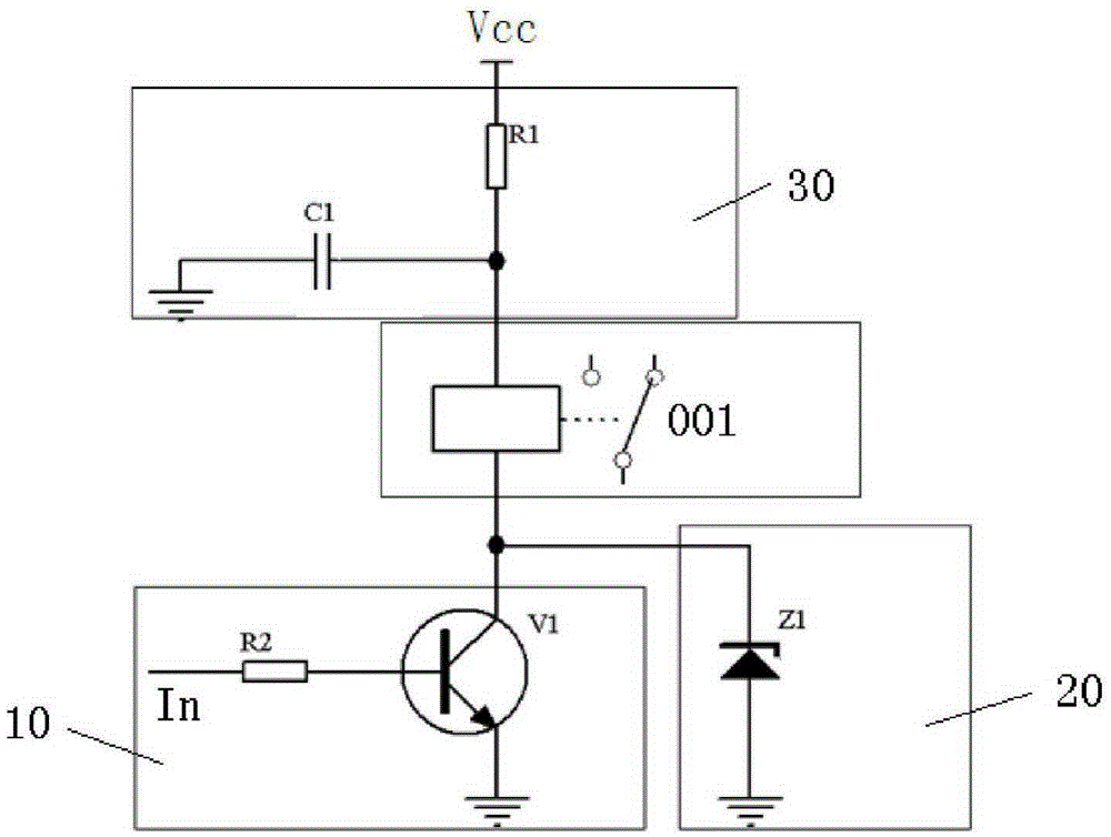
The invention relates to a direct-current electromagnetic relay drive circuit and a drive method therefor. The drive circuit comprises a voltage source, a closed circuit and a power consumption suppression circuit, wherein the relay is arranged between the voltage source and the closed circuit; the power consumption suppression circuit is arranged between the voltage source and the relay; the voltage source is used for providing a direct-current power supply voltage which is higher than a rated voltage value of a relay coil; the closed circuit comprises a drive transistor; the transistor is conducted on the basis of a drive control signal for closing the relay, so that a current path is provided for electrifying the relay coil; the power consumption suppression circuit comprises an energy storage capacitor and a power consumption suppression resistor; the energy storage capacitor is used for storing the power supply voltage before the drive transistor is conducted, and releasing the stored voltage to the relay coil after the drive transistor is conducted; and the power consumption suppression resistor is arranged to suppress the voltage of the coil no more than a rated value after the current of the coil reaches the rated value.

Description

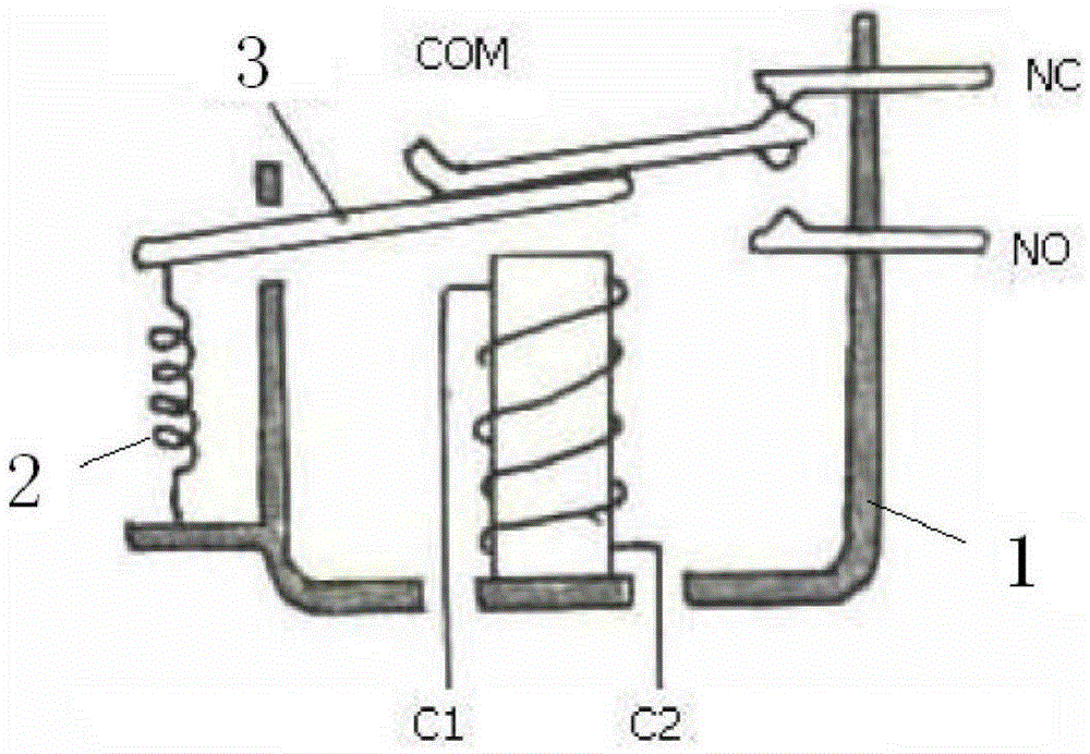
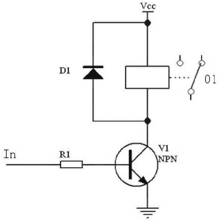
technical field [0001] The invention relates to the field of design and manufacture of electronic equipment, in particular to a DC electromagnetic relay drive circuit and a drive method for power supply on-off and signal control. Background technique [0002] Relays are divided into electromagnetic relays and solid state relays (semiconductor devices). Electromagnetic relays are divided into AC electromagnetic relays and DC electromagnetic relays according to the current characteristics required by their relay coils. This article discusses the control of DC electromagnetic relays. [0003] In terms of electric energy and power conversion and signal control, DC electromagnetic relays and contactors are often used to control the on-off of high-current signals or to play the role of electrical isolation of signals. [0004] The structure of DC electromagnetic relay is as follows: figure 1 As shown, it includes: outer frame 1, spring 2, armature 3, electromagnet 4, contacts a...

Claims


Application Information

Patent Timeline
Patent Type & Authority Applications(China)
IPC IPC(8): H01H47/00
CPCH01H47/00
Inventor 于小冬任涛
Owner BEIJING YAAO BOXIN COMM TECH CO LTD
Learn More