
Production and separation method for flexible substrate

A technology of flexible substrates and separation methods, which is applied in semiconductor/solid-state device manufacturing, electrical components, electric solid-state devices, etc., can solve the problems of unsatisfactory yield and quality of flexible substrates, high cost of flexible OLED preparation, and achieve supporting facilities Improvement, wide application range, and the effect of reducing equipment procurement costs and process costs

Active Publication Date: 2016-03-23
SHANGHAI UNIV
View PDF4 Cites 14 Cited by
  • Summary
  • Abstract
  • Description
  • Claims
  • Application Information

AI Technical Summary

Problems solved by technology

The preparation cost of flexible OLED is high, especially the yield and quality of flexible substrate are not ideal enough

Method used


Image

  • Production and separation method for flexible substrate
  • Production and separation method for flexible substrate
  • Production and separation method for flexible substrate

Examples


Embodiment 1

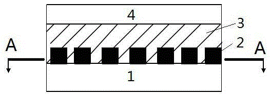
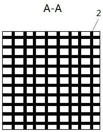
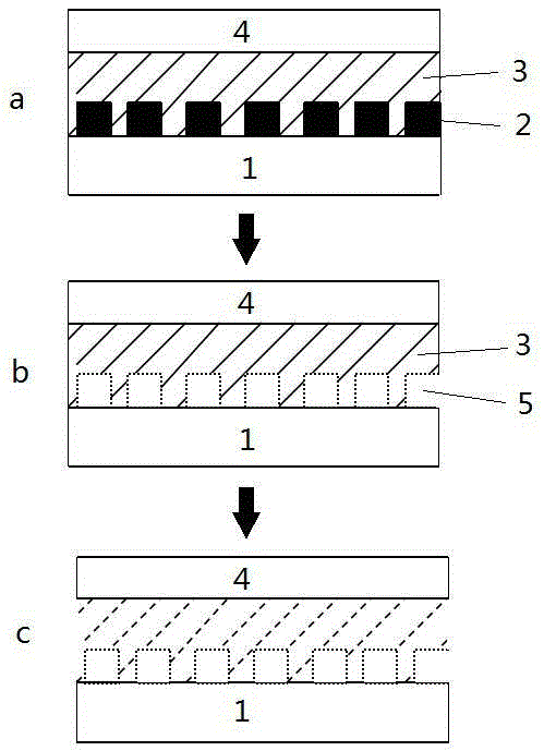
[0025] In this example, see Figure 1~3 , a preparation and separation method of a flexible substrate, using a rigid material substrate 1, the rigid material substrate 1 adopts a glass substrate, and sequentially prepare a grid-shaped continuous frame layer 2, a connecting layer 3 and a flexible substrate on the rigid material substrate 1 4. Form a grid-like layout, between the rigid material substrate 1 and the flexible substrate 4, combine the connecting layer 3 and the continuous frame layer 2 to form a combined layer, and fill the material for preparing the connecting layer 3 into the continuous frame layer 2, the upper surface of the combination layer is used as the surface of the carrier substrate for preparing the flexible substrate 4, and then the flexible substrate 4 is prepared on the upper surface of the combination layer, and then the subsequent film layer is prepared on the flexible substrate 4, wherein the continuous The frame layer 2 remains stable during the pr...

Embodiment 2

[0034] This embodiment is basically the same as Embodiment 1, especially in that:

[0035]In this embodiment, when the flexible substrate 4 is separated, the material of the continuous frame layer 2 is decomposed by using UV irradiation method, so that a grid-like continuous channel 5 is formed in the combined layer, so as to facilitate the subsequent implementation of the connecting layer 3. etch removal process. The method of this embodiment adopts the method of preparing a combined layer composed of a connecting layer 3 and a grid-shaped continuous frame layer 2 between a glass substrate and a flexible substrate 4, wherein the continuous frame layer 2 is stable under the conditions of the subsequent film layer preparation, and is stable in a specific treatment. Under the decomposition, the continuous frame layer 2 is decomposed and morphologically changed by changing the reaction conditions of UV irradiation, and a grid-like continuous channel 5 is formed in the connecting ...


PUM


Abstract

The invention discloses a production and separation method for a flexible substrate. The method comprises: preparing a combination layer composed of a connection layer and a grid-shaped continuous frame layer between a rigid substrate and a flexible substrate, wherein the continuous frame layer is stable under the preparation condition of subsequent corresponding devices or film layers and is decomposed by specific treatment; changing a reaction condition to realize decomposition or morphologic change of the continuous frame layer; and forming a grid-shaped gas passage in the connection layer to remove the connection layer in a plasma atmosphere so as to finish the separation of the flexible substrate. According to the separation method, not only can the stripping of the substrate be finished on the premise of ensuring the intact substrate but also a mature glass substrate based film layer preparation process and a matching device can be fully utilized, so that the method has promotional values.

Description

technical field [0001] The invention relates to a method for preparing an organic electroluminescent device, in particular to a method for preparing a flexible OLED, which is applied to the technical fields of electronic devices such as flexible displays and wearable devices. Background technique [0002] With the development of science and technology, more and more new things come into our life, and people's requirements for equipment are also increasing day by day. , OLED-based flexible display technology and related fields of wearable devices have a wider development space, and a series of related technologies based on flexible substrates have also received corresponding attention. [0003] The emergence of wearable devices has put forward higher requirements for the shape of the device, which needs to meet the wearing habits of the human body. Therefore, the display elements it is equipped with must also have flexible characteristics, so flexible display components based...

Claims


Application Information

Patent Timeline
IPC IPC(8): H01L21/77
CPCH01L27/1262
Inventor 陈龙龙张建华张帅
Owner SHANGHAI UNIV
Learn More