
Micro-grid inverter droop control method based on adjustable virtual impedance

A virtual impedance and control method technology, applied in the direction of irreversible DC power input conversion to AC power output, sustainable manufacturing/processing, AC network circuits, etc., can solve the problem of different voltage distribution, adverse effects on control performance, power output Active and reactive components cannot be decoupled to achieve the effect of improving operating performance and stability

Inactive Publication Date: 2016-03-23
CENT SOUTH UNIV
View PDF4 Cites 24 Cited by
  • Summary
  • Abstract
  • Description
  • Claims
  • Application Information

AI Technical Summary

Problems solved by technology

However, due to the different output impedance characteristics and connection impedance of each power supply, the control methods and reactive power adjustment methods are different, and the voltage distribution at each point of the system is different. Especially in the low-voltage microgrid, the resistive component of the line impedance cannot be ignored, making the power output The active and reactive components cannot be decoupled, which will adversely affect the control performance of the above-mentioned "power-voltage-current" three-loop droop control method
By designing the virtual impedance, the inductive component of the output impedance in the parallel system can account for the absolute proportion, so as to meet the application conditions of the droop control and improve the coupling, and reduce the influence of the actual impedance difference, but this is at the cost of a greater voltage drop, and The quality of virtual impedance design directly affects the accuracy of reactive power distribution between inverter-type power supplies operating in parallel under inductive line conditions

Method used


Image

  • Micro-grid inverter droop control method based on adjustable virtual impedance
  • Micro-grid inverter droop control method based on adjustable virtual impedance
  • Micro-grid inverter droop control method based on adjustable virtual impedance

Examples


Embodiment Construction

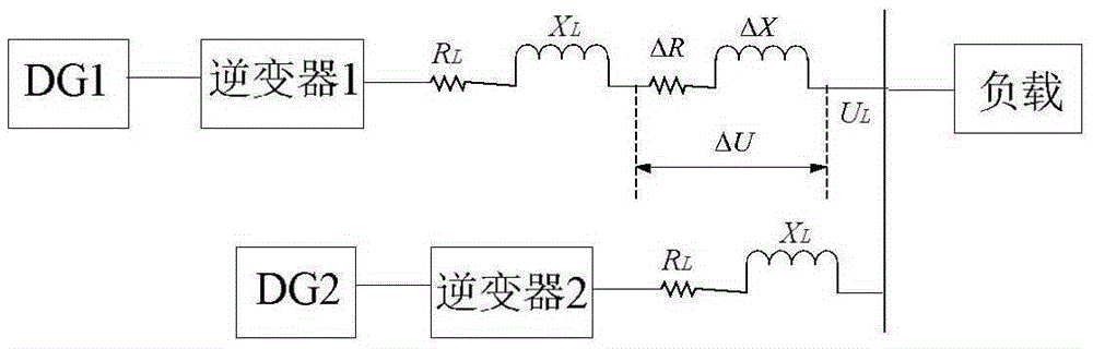
[0028] figure 1 It is the equivalent circuit diagram of the microgrid inverter. The main parameters of the system are as follows: DG1 and DG2 are DC voltages, which simulate the output of a micro-source, and the DC voltage value is 500V. Control the peak value of the output voltage of each inverter to 311V and the frequency to 50Hz. The load is a resistive load with a resistance value of 10Ω and an inductance value of 1mH. Line impedance is R L =0.5Ω,X L =1mH, the line resistance changes due to the influence of the external environment, ΔR is 0.3Ω, ΔX is 1.5mH.

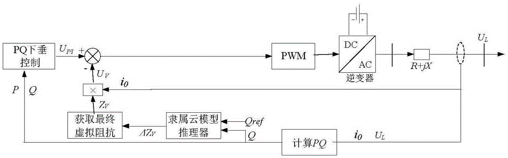
[0029] Such as figure 2 As shown, the control steps of the present invention are:

[0030] Step 1: Detect the output current i of the inverter 0 And output voltage u L , To obtain active power P and reactive power Q.

[0031] Step 2: Set the reference value Q of reactive power ref .

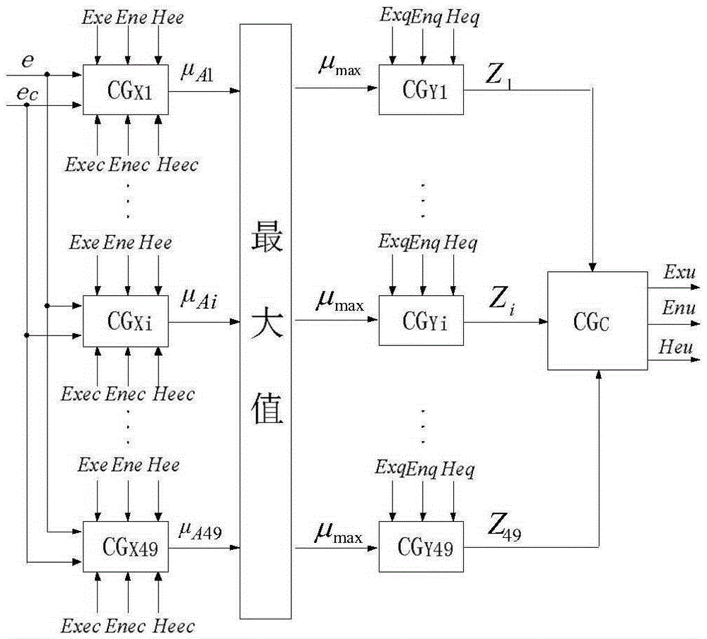
[0032] Step 3: Use the cloud model reasoner to determine the virtual impedance Z V Make online adjustments. Reactive power Q and Q ref As...


PUM


Abstract

The present invention discloses a micro-grid inverter droop control method based on adjustable virtual impedance. Inverter output current i0 and common point voltage UL are detected and active power P and reactive power Q are obtained, and a traditional PQ droop control algorithm is used to obtain voltage Upq. An inferer based on a membership cloud model is designed, the error of the reactive power and an error variable quantity are taken as the input signal of the inferer, and through a corresponding inference rule, the adjustable virtual impedance delta ZV is obtained through inference. The adjustable virtual impedance and initial virtual impedance are added to obtain final virtual impedance ZV. The final virtual impedance ZV and the inverter output current are multiplied, then the result of the multiplication and the voltage Upq are subtracted, an obtained signal is sent PWM, and the on and off control of a power device in an inverter is realized. The power outer ring controller of a micro source is designed according to a droop characteristic, the power automatic distribution function of the micro source is realized, the real-time adjustment of the virtual impedance is realized by using the membership cloud model, and the power sharing between micro sources is realized.

Description

Technical field [0001] The invention relates to the technical field of distributed power generation and power electronics, in particular to a droop control method of a microgrid inverter based on an adjustable virtual impedance. Background technique [0002] Distributed Generation System (Distributed Generation System) is an independent power system compatible with the environment. There are multiple energy sources such as wind, solar, fuel cells, micro gas turbines, and energy storage systems. It can also be connected to the micro public grid in the form of parallel inverters, which is of great significance to promote the efficiency of energy in my country. It has flexible variable load peak regulation performance, can meet the special requirements of power systems and users, and can provide high power supply reliability for remote users or commercial areas. Saving investment in power transmission and transformation, especially suitable for the use of renewable energy, is one o...

Claims


Application Information

Patent Timeline
IPC IPC(8): H02J3/38H02J3/50H02M7/48
CPCY02P80/14H02J3/381H02J3/50H02M7/48
Inventor 黎燕樊晓平彭劲杰
Owner CENT SOUTH UNIV
Learn More