Dual-long-secondary and primary permanent magnetic field modulation linear motor for oil pumping unit

A technology of linear motors and pumping units, which is applied in the direction of electromechanical devices, electrical components, electric components, etc., can solve the problems of large amount of permanent magnets and high processing costs, and achieve the effects of low processing costs, convenient mechanical assembly, and high thrust density

Active Publication Date: 2016-03-23
CHINA UNIV OF PETROLEUM (EAST CHINA)
View PDF10 Cites 3 Cited by
  • Summary
  • Abstract
  • Description
  • Claims
  • Application Information

AI Technical Summary

Problems solved by technology

In order to solve the problems of large amount of permanent magnets and high processing costs in the secondary long stator structure of the permanent magnet synchronous linear motor used in the existing linear motor pumping unit for oil extraction, th

Method used


Image

  • Dual-long-secondary and primary permanent magnetic field modulation linear motor for oil pumping unit

Examples


Embodiment 1

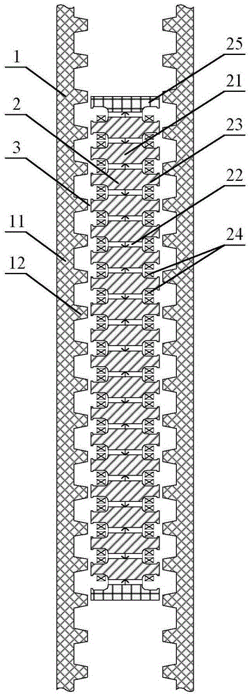
[0035] A bilateral long secondary primary permanent magnet type field modulated linear motor for an oil pumping unit, comprising two long secondary stators 1 arranged symmetrically opposite each other, and a short primary mover arranged between the two long secondary stators 1 2 and an air gap 3 provided between the short primary mover 2 and the long secondary stator 1;

[0036] The short primary mover 2 includes primary iron cores 21 arranged equidistantly along the moving direction, primary permanent magnets 22 embedded between adjacent primary iron cores 21, and the width of the primary iron cores 21 is greater than the width of the primary permanent magnets 22 Primary teeth 23 are formed on both sides of the primary iron core 21 in the width direction, and armature windings 24 are nested on the primary teeth 23 .

[0037] The long secondary stator 1 includes a flat secondary iron core 11 and secondary salient poles 12 equidistantly arranged on the inner surface of the flat...

Embodiment 2

[0040] As described in Example 1, a bilateral long secondary primary permanent magnet type field modulated linear motor for an oil pumping unit is different in that the number of primary teeth 23 on one side is: N p , The number of pole pairs wound by the armature winding 24: p w , The distance between the centers of the primary teeth 23 adjacent to one side: τ p Distance from the center of the adjacent secondary salient pole 12: τ s , satisfy the following relation (I):

[0041] N p ·τ p =(N p / 2+p w )·τ s (I)

[0042] In formula (I), N p =6k, k is a positive integer; the number of blocks of the primary permanent magnet 22 is N p +1.

Embodiment 3

[0044]A kind of bilateral long secondary primary permanent magnet field modulation linear motor for a pumping unit as described in Embodiment 1 and 2, the difference is that the end faces of the primary permanent magnets 22 at both ends of the short primary mover 2 along the moving direction Balance teeth 25 are respectively arranged on them.


PUM


Abstract

The invention discloses a dual-long-secondary and primary permanent magnetic field modulation linear motor for an oil pumping unit. The motor comprises two long secondary stators arranged symmetrically and oppositely, a short primary rotor arranged between the two long secondary stators, and air gaps formed between the short primary rotor and the long secondary stators, wherein the short primary rotor comprises primary iron cores arranged at equal intervals in a motion direction, and primary permanent magnets embedded between the adjacent primary iron cores; the primary iron cores are wider than the primary permanent magnets, so that primary teeth are formed on two sides of each primary iron core in the width direction; and armature windings are nested on the primary teeth. According to the motor, the armature windings and the permanent magnets are all arranged in the short primary rotor; the long secondary stators only adopt salient pole flat plate structures composed of magnetic materials; a primary magnetic field is modulated by air gap permeance changes caused by secondary salient poles to realize electromechanical energy conversion; and the motor has the characteristics of simple structure, high reliability, low cost and high thrust density.

Description

technical field [0001] The invention relates to a double-sided long secondary primary permanent magnet field modulation linear motor for an oil pumping unit, and belongs to the technical field of linear motors for oil pumping. Background technique [0002] The beam pumping unit utilizes electric energy to convert it into rotary motion, and then converts it into linear reciprocating motion through a four-bar linkage after deceleration. The energy loss of its transmission system is as high as 28%. In addition, the rotation characteristic causes a large starting torque, and the system efficiency is generally not good. More than 30%. The linear motor pumping unit directly converts electrical energy into linear reciprocating motion, which simplifies the mechanical transmission process and effectively improves the efficiency. Moreover, when the stroke is increased, the overall size and weight of the whole machine will increase very little, especially the pumping parameters can be ...

Claims


Application Information

Patent Timeline
IPC IPC(8): H02K41/03
CPCH02K41/033
Inventor 李祥林刘圣炜王玉彬
Owner CHINA UNIV OF PETROLEUM (EAST CHINA)
Why Eureka
Try Eureka