Supercharge Your Innovation With Domain-Expert AI Agents!

Heat exchanger diaphragm seal welding seam cutting machine and cutting method

A diaphragm seal and heat exchanger technology, which is applied in the direction of metal processing machinery parts, large fixed members, milling machine equipment, etc., can solve the problem of easy damage to the end of the tube box and the diaphragm pad, the inconvenience of maintenance inside the tube box, and the reassembly of the tube box Problems such as the difficulty of the end and the diaphragm pad, etc., achieve the effect of simple structure, simple cutting method, and low cost

Active Publication Date: 2018-04-20
THE CHALLENGE PETROCHEM MACHINERY CORP
View PDF7 Cites 0 Cited by
  • Summary
  • Abstract
  • Description
  • Claims
  • Application Information

AI Technical Summary

Problems solved by technology

[0005] However, due to the sealing welding between the edge ring of the spherical diaphragm sealing disc and the end of the pipe box, it brings a lot of inconvenience to the inspection and maintenance inside the pipe box, resulting in the need to remove the sealing weld. Or grinding and cutting with a grinder will not only ignite the remaining medium in the structure, but also easily damage the end of the pipe box and the diaphragm pad itself, making it difficult to reassemble the end of the pipe box and the diaphragm pad. Therefore, in order to better promote the application of spherical Diaphragm sealing technology, it is necessary to avoid the above-mentioned technical problems caused by the use of fire cutting or grinding and cutting technology to remove the sealing weld

Method used


Image

  • Heat exchanger diaphragm seal welding seam cutting machine and cutting method
  • Heat exchanger diaphragm seal welding seam cutting machine and cutting method
  • Heat exchanger diaphragm seal welding seam cutting machine and cutting method

Examples


Embodiment 1

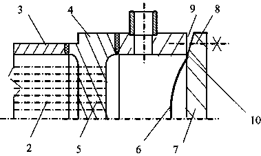
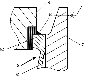
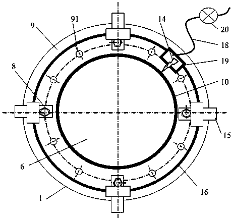
[0032] One of the specific implementations of the heat exchanger diaphragm seal welding seam cutting machine of the present application, the heat exchanger diaphragm sealing seam cutting machine is applied to the cutting of the heat exchanger diaphragm sealing seam 10, referring to the prior art figure 1 with figure 2 As shown, the heat exchanger includes a tube bundle 2, a tube shell 3 and a tube box 4, and the tube bundle 2 is pierced through the tube sheet 5, wherein: the tube box 4 is provided with a spherical diaphragm sealing disc 6, and the spherical diaphragm sealing disc 6 is arranged in the tube box Between the end 9 and the pipe box end cover 7; the spherical diaphragm sealing disc 6 includes a spherical membrane 61 arranged in the middle and a flat edge ring 62 arranged along the outer circumference of the spherical membrane 61; the flat edge ring 62 It is sealed with the pipe box end 9 through a sealing weld 10 ; the pipe box end 9 is fixedly connected with the p...

Embodiment 2

[0039] The second specific embodiment of the heat exchanger diaphragm seal welding seam cutting machine of the application, the main technical solution of this embodiment is the same as that of embodiment 1, and the features not explained in this embodiment adopt the explanation in embodiment 1, No further details will be given here. The difference between this embodiment and embodiment 1 is that the reference image 3 As shown, the frame 12 is provided with an adjustment spoke 15 with a chute in the middle, and the frame 12 is fixed to the pipe box end 9 through the adjustment spoke 15 . Generally speaking, the 9 manholes at the end of the pipe box are relatively fixed and designed to vary from 500mm to 700mm. Adjusting the radial expansion and contraction of the spokes 15 can be applied to the range of change from 600mm to 800mm in the center circle of the threaded hole 91 at the end of the pipe box 9. , but the above variation range can be changed according to design requi...

Embodiment 3

[0042] The third specific embodiment of the heat exchanger diaphragm seal welding seam cutting machine of the present application, the main technical solution of this embodiment is the same as that of embodiment 1, and the features not explained in this embodiment adopt the explanation in embodiment 1, No further details will be given here. The difference between this embodiment and Embodiment 1 is that the installation of the frame 12 and the pipe box 4 does not need to use the threaded hole 91 at the end 9 of the pipe box. Instead refer to Figure 5 As shown, the frame 12 is fastened to the pipe box outer circle 1 of the pipe box end 9 by tightening bolts 21 . If necessary, depending on the situation of the threaded holes 91, the number of tightening bolts 21 can be appropriately increased to enhance the connection rigidity.


PUM


Abstract

The invention discloses a diaphragm seal weld joint cutting machine for a heat exchanger and a cutting method. The cutting machine comprises a rack arranged at the end of a pipe box, a ring guide rail arranged on the rack and a cutting device. Guide rail teeth are arranged on the ring guide rail. The cutting device comprises a knife rest, a cutting knife, a knife feeding device and a guide rail gear which is arranged on the knife rest and matched with the guide rail teeth, wherein the cutting knife and the knife feeding device are arranged on the knife rest. Under the driving action of a power source, the cutting knife rotates along the ring guide rail. Compared with the prior art, the cutting machine can effectively avoid structural damage caused when seal joints are removed, a diaphragm washer can be repeatedly recycled, the utilizing rate is high, meanwhile, the structure is simple, the manufacturing period is short, and cost is low. The cutting method includes the steps that the cutting machine is fastened to a threaded hole in the end of the pipe box through a stud nut of the pipe box of the heat exchanger, or the cutting machine is fastened to the outer circle face of the end of the pipe box through a tightening bolt. The cutting method is simple and easy to operate, the end of the pipe box and the diaphragm washer are not prone to damage, and the diaphragm seal weld joint cutting machine for the heat exchanger and the cutting method can be industrially popularized on a large scale.

Description

technical field [0001] This application relates to the technical field of shell and tube heat exchangers dedicated to heat exchange and energy-saving equipment for petroleum refining and chemical industry, coal chemical industry, chemical fertilizer industry, air conditioning, air cooling, and electric power facilities, especially related to heat exchanger diaphragm seal welding seam cutting machine and Excision method. Background technique [0002] In the prior art, the tube-and-tube heat exchanger is the most widely used heat exchanger, widely used in the fields of chemical industry, petroleum, medicine, food, light industry, metallurgy, coking, etc. Convective heat transfer of "steam-steam" and "steam-liquid" heat exchange, as well as heat exchange and condensation processes such as steam condensation and liquid evaporation heat transfer. [0003] Tube-and-tube heat exchangers in the prior art are usually composed of main components such as tube bundles, tube shells, and...

Claims


Application Information

Patent Timeline
Patent Type & Authority Patents(China)
IPC IPC(8): B23B39/02B23Q1/01B23C3/02
CPCB23B39/02B23C3/02B23Q1/015B23Q1/017
Inventor 陈孙艺
Owner THE CHALLENGE PETROCHEM MACHINERY CORP
Features
  • R&D
  • Intellectual Property
  • Life Sciences
  • Materials
  • Tech Scout
  • Unparalleled Data Quality
  • Higher Quality Content
  • 60% Fewer Hallucinations
Learn More