Ball end mill

A ball end mill and tool technology, which is applied in the field of metal cutting, can solve the problems of chip tolerance at the cutting edge, limited chip removal capacity, uneasy cutting, restricting the improvement of cutting performance of the tool, etc., so as to increase the chip breaking separation. ability, increased cutting sharpness, and the effect of enhanced chip holding capacity

Active Publication Date: 2016-03-30
ZHUZHOU CEMENTED CARBIDE CUTTING TOOLS CO LTD
View PDF7 Cites 10 Cited by
  • Summary
  • Abstract
  • Description
  • Claims
  • Application Information

AI Technical Summary

Problems solved by technology

[0005] First, the cutting edge of the universal ball end mill has an angle between 0° and 5° with the central axis. Due to the limitation of its helical structure, the rake angle of the cutting edge in this range is -1°~- Change between 10°, so the rake angle at the cutting edge near the center of the ball head of the ball end mill is negative, and the cutting is not brisk during processing, resulting in rapid tool wear and short tool life
[0006] Second, usually the bottom of the chip flute of the general-purpose ball end mill is made into a convex arc edge shape. Due to the narrow chip space at the cutting edge near the center of the ball end mill, the tolerance at the cutting edge at the center of the ball end Chips and chip removal capabilities are limited, and cutting efficiency cannot be greatly improved, which restricts the improvement of tool cutting performance
[0007] Third, the universal ball end mill forms a chisel edge at the center of the ball head, so that the center of the ball head forms a cutting edge, and the surface quality of the center of the ball head is also improved and improved, but at the same time it will form a chisel edge at the border of the chisel edge, The strength of the chisel edge boundary cannot be guaranteed. When the ball end mill is end milled, it is easy to generate stress concentration and chipping, which reduces the cutting life of the ball end mill and affects the cutting stability of the ball end mill.

Method used


Image

  • Ball end mill
  • Ball end mill
  • Ball end mill

Examples


Embodiment Construction

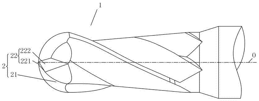
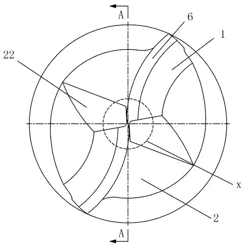
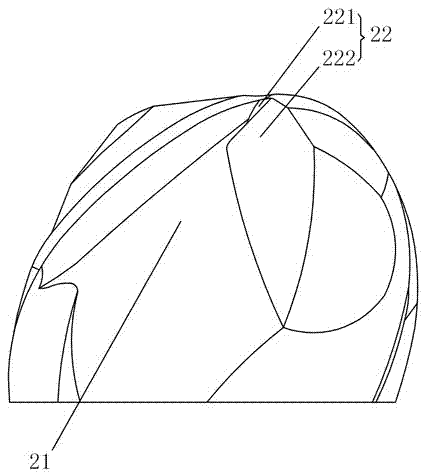
[0026] Figure 1 to Figure 6 Shown is a ball end mill embodiment of the present invention, the ball end mill includes a cylindrical tool body 1 with the central axis O as the center of rotation, the outer circumference of the cutting part of the tool body 1 is provided with a The chip flute 2 at the end, the chip flute 2 intersects with the flank 6 set at the cutting end to form an end cutting edge, and there are more than two chip flutes 2 and the flank 6, and the number is equal. The chisel edge 4 is formed by the intersection of the adjacent flank face 6. The chip flute 2 includes a main groove 21 and a deep groove 22. The main groove 21 intersects with the flank face 6 to form an arc cutting edge 7. The inclined plane 222 is formed, the small rake face 221 intersects with the flank face 6 to form a plane cutting edge 5, the inclined plane 222 intersects with the arc-shaped bottom of the main groove 21, and the depth of the inclined plane 222 is greater than the depth of th...


PUM


Abstract

The invention discloses a ball end mill which comprises a cylindrical cutter main body with the central shaft as a rotation center, wherein two or more chip grooves which extend to the cutting end part are formed in the outer circumference of the cutting part of the cutter main body and are intersected with two or more back cutter surfaces arranged on the cutting end part to form end cutting blades; the amount of the chip grooves is equal to that of the back cutter surfaces; the adjacent two back cutter surfaces are intersected to each other to form a transverse blade; the chip grooves are composed of a main groove and a deep groove; the main groove is intersected with the corresponding back cutter surface to form an arch-shaped cutting blade; the deep groove is composed of a small front cutter surface and an inclined plane; the small front cutter surface is intersected with the corresponding back cutter surface to form a plane cutting blade; the inclined plane is intersected with the arch-shaped bottom of the main groove; the depth of the inclined plane is larger than that of the main groove; the arch-shaped cutting blade is in smooth connection with the plane cutting blade to form an end cutting blade; and the end part of the transverse blade is intersected with the middle part of the plane cutting blade. The ball end mill can ensure the boundary strength of the transverse blade and improve the sharpness of the cutting blade and the chip discharge capacity.

Description

technical field [0001] The invention relates to the field of metal cutting, in particular to a ball end mill used for forming parts such as mold cavities and aviation blades. Background technique [0002] Usually, the ball end mill is widely used in the cutting process of the cavity surface of the mold or the root cleaning process of the airfoil profile of aerospace difficult-to-machine materials, and the ball end mill near the center of the ball head of the ball end mill needs to be frequently used for cutting Edge processing (this processing method is referred to as end milling). [0003] As we all know, the cutting speed of the universal ball end mill increases sequentially from the center of the ball end to the outer peripheral edge, and the linear speed of the ball end cutting edge at the axis is zero. When using a ball end mill for end milling, within the range of 0° to 5° included with the central axis, it can be approximately considered that the ball end cutting edg...

Claims


Application Information

Patent Timeline
Patent Type & Authority Applications(China)
IPC IPC(8): B23C5/10
CPCB23C5/1018B23C2210/04B23C2210/0442B23C2210/40B23C2222/28
Inventor 肖跃勇方曙璋李屏
Owner ZHUZHOU CEMENTED CARBIDE CUTTING TOOLS CO LTD
Why Eureka
Try Eureka