Machining method for turbine work blade

A technology of mechanical processing and blades, which is applied in the field of mechanical processing of aero-engines, can solve the problems of low production quality and production efficiency of turbine blades, and achieve the effects of high blade processing quality, reliable positioning, and strong practicability

Active Publication Date: 2016-03-30
AECC AVIATION POWER CO LTD
View PDF9 Cites 30 Cited by
  • Summary
  • Abstract
  • Description
  • Claims
  • Application Information

AI Technical Summary

Problems solved by technology

At present, the mechanical processing of turbine working blades is mainly to machine the mortise teeth and edge plates. The airfoil profile is guaranteed by precision casting, and the production quality and production efficiency of turbine blades are not high.

Method used


Image

  • Machining method for turbine work blade
  • Machining method for turbine work blade
  • Machining method for turbine work blade

Examples


Embodiment Construction

[0024] The present invention will be further explained below in conjunction with specific embodiments and accompanying drawings.

[0025] The turbine blade processing technology of the present invention is as follows: degreasing→blade precise positioning→wax filling→grinding tenon teeth and tooth exhaust side→wax removal→melting low melting point alloy→pollution removal→grinding tenon tooth bottom→grinding edge plate and teeth Air intake side→fluorescent inspection→comprehensive inspection→processing air film holes→cleaning→storage.

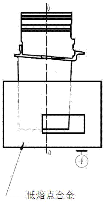
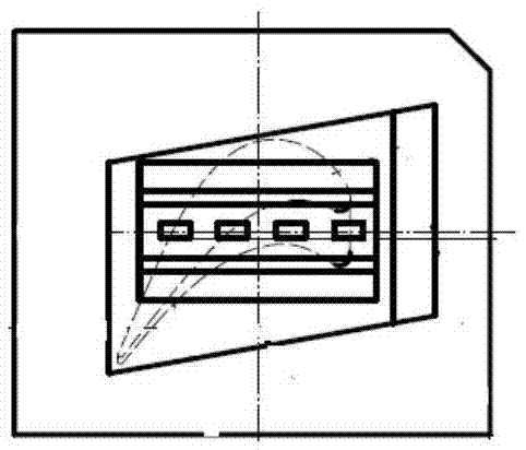
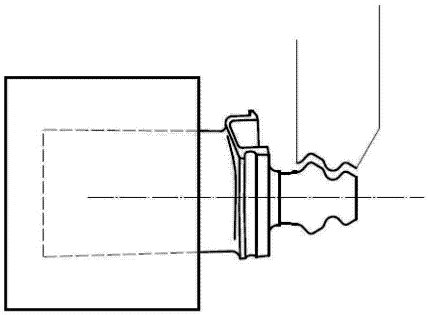
[0026] Degreasing is to clean up the oil stains attached to the wool from the warehouse. see Figure 1a and Figure 1b , the precision positioning of the blade is cast low-melting point alloy, and the six-point positioning reference of the blade body surface is converted to the six-point positioning reference of the casting block. The positioning is reliable and easy to clamp during machining. Adhesive tape seals all the holes on the blade body...


PUM


Abstract

The invention discloses a machining method for a turbine work blade. The machining method for the turbine work blade aims to improve the production quality and production efficiency of the turbine blade and meet the machining and use requirements for the turbine work blade of an aero-engine. According to the technical scheme, the machining process comprises the steps of oil removing, precision positioning of the blade, wax filling, grinding of tenon teeth and the tooth exhaust side, wax removing, melting of low-melting-point alloy, pollutant removing, grinding of the bottoms of the tenon teeth, grinding of a marginal plate and the tooth air inlet lateral face, fluorescent inspection, comprehensive detection, machining of film holes, cleaning and storage. A five-axis numerical control creep feed grinder is adopted, the turbine work blade machining process with the advanced manufacturing technology is achieved, novelty, creativity and practicability are high, the process route is arranged reasonably, the production efficiency is high, the blade machining quality is high, the requirement for production of a large batch of turbine blades can be met, and the machining method can be widely used for machining turbine work blades of aero-engines.

Description

technical field [0001] The invention relates to the machining technology of aero-engines, in particular to a machining method for turbine working blades. Background technique [0002] The working blades of the turbine are located in the part of the aeroengine with the highest temperature, the most complex stress and the harshest environment, and are known as the "Pearl in the Crown". The exterior structure is composed of blade body, edge plate, transition section, mortise teeth, gas film hole, split hole, etc., and the inner cavity is hollow. It has complex shapes, high requirements, and difficult processing, and has always been the key to the production of various aero-engine factories. The main materials are DZ125, K403, DD5, DD6, K417, etc. At present, the mechanical processing of turbine working blades is mainly to machine the mortise teeth and edge plate parts. The airfoil profile is guaranteed by precision casting, and the production quality and production efficiency...

Claims


Application Information

Patent Timeline
Patent Type & Authority Applications(China)
IPC IPC(8): B23P15/02
CPCB23P15/02
Inventor 刘海滨崔保卫张澜禹梁忠效党玉芳王冬王瑞科刘洁
Owner AECC AVIATION POWER CO LTD
Why Eureka
Try Eureka