Reflection crack repairing structure and reflection crack repairing process

A reflective crack and process technology, applied in the field of road surface reflective crack repair technology, can solve problems such as high investment cost, reduced road quality, rutting disease, etc. Effect

Inactive Publication Date: 2016-03-30
JIANGSU SINOROAD ENG TECH RES INST CO LTD
View PDF4 Cites 4 Cited by
  • Summary
  • Abstract
  • Description
  • Claims
  • Application Information

AI Technical Summary

Problems solved by technology

However, as the thickness of the asphalt layer increases, rutting will inevitably occur, reduce the quality of the road surface, and the investment cost will be higher

Method used


Image

  • Reflection crack repairing structure and reflection crack repairing process

Examples


Embodiment 1

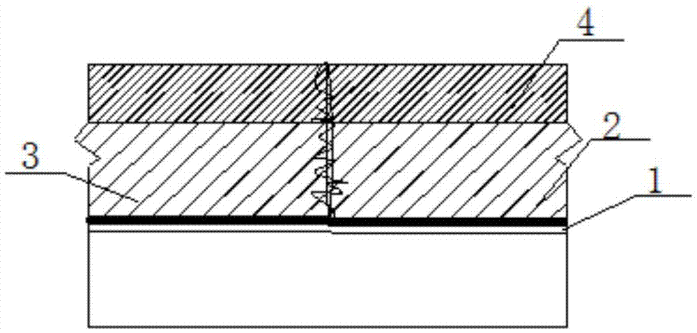
[0028] The reflective crack repair process of the present invention firstly adjusts the width of the slotting machine tool according to the designed crack slotting width, and debugs the equipment to ensure that the equipment is working normally; secondly, the equipment must be pre-operated before starting the slotting; finally, it is carried out along the crack Slotting, according to the designed slotting depth, adjust the depth adjuster to reach the designed depth. When grooving, ensure that the centerline of the groove is consistent with the centerline of the crack. Regardless of whether the crack has been grooved or not, there are more or less moisture, dust, debris and debris in the crack. In order to ensure that the sealing material has good adhesion to the wall of the crack (or groove), The wall of the crack (or groove) should be thoroughly cleaned and completely dry. The method of seam cleaning generally uses compressed air blowing, sandblasting, steel wire brushing, an...

Embodiment 2

[0031] With reference to the construction method of Example 1, the reflective crack repair process of the present invention is applied to K67+661 in the upward direction of a certain arterial road. The test section is about 10m long, milling at 50cm on both sides of the crack, and the milling depth is 9cm, and then backfilled 6.5 cm rock asphalt modified high modulus asphalt mixture, 2.5cm U-Pave10 asphalt mixture.

Embodiment 3

[0033] With reference to the construction method of Example 1, the reflective crack repair process of the present invention is applied to a certain arterial road to K67+712, the test section is about 11m long, milling at 70cm on both sides of the crack, the milling depth is 10cm, and then backfilling 7.5cm Rock asphalt modified high modulus asphalt mixture, 2.5cm U-Pave10 asphalt mixture.

[0034] Comprehensive examples 1 to 3, after the later on-site investigation and testing, the treated pavement basically has no reflection cracks. Understand the dynamics of road surface changes, and adopt the test of bearing capacity, and the monitoring and testing meet the requirements of relevant regulations.


PUM


Abstract

The invention discloses a reflection crack repairing structure and a reflection crack repairing process. The reflection crack repairing structure comprises a waterproof adhesive layer, a fiberglass-polyester paving mat anti-crack layer, a first backfill layer and a second backfill layer, wherein the waterproof adhesive layer is arranged on a grooved bottom surface of a reflection crack; the fiberglass-polyester paving mat anti-crack layer is arranged on the upper surface of the waterproof adhesive layer; the first backfill layer is arranged on the upper surface of the fiberglass-polyester paving mat anti-crack layer; and the second backfill layer is arranged on the upper surface of the first backfill layer. By milling materials around the crack and backfilling the fiberglass-polyester paving mat anti-crack layer and backfill, the reflection crack repairing structure disclosed by the invention has favorable integrity, continuity and durability. When the reflection crack repairing structure is applied to a pavement structure, the reflection crack repairing structure has the functions of isolation, seepage prevention, filtration, drainage and the like, can improve the resistance to fatigue cracking of an asphalt surface course, can prevent the reflection crack and deformation resistance, and can improve the use quality of a semi-rigid base asphalt pavement with obviously insufficient old road intensity, large traffic flow, frequent heavy overload vehicles and severe cracking, thereby prolonging the service life of the pavement structure.

Description

Technical field [0001] The invention relates to a repairing process for reflective cracks on a road surface, in particular to a reflective crack repairing structure and a repairing process. Background technique [0002] Reflective cracking is a common disease phenomenon in asphalt pavement, which is caused by cracks in the base layer. With the rapid development of road construction in our country, the problem of reflective cracks on asphalt pavements is becoming more and more serious. Road maintenance and maintenance require more and more works. How to reduce and prevent reflective cracks on asphalt pavements has become an urgent problem for road construction projects. . After cracks appear on existing built roads, asphalt is usually used to fill and maintain them. If the cracked road section is large, after the large area is removed, the asphalt concrete material is used for surface treatment to temporarily solve the problem of road cracks. However, due to the existence of th...

Claims


Application Information

Patent Timeline
Patent Type & Authority Applications(China)
IPC IPC(8): E01C7/18E01C11/00
CPCE01C7/187
Inventor 关永胜耿磊周文费燕华
Owner JIANGSU SINOROAD ENG TECH RES INST CO LTD
Why Eureka
Try Eureka