
Deep refrigeration regulating valve with piston pressure self-sealing and positioning functions

A piston pressure, self-sealing technology, used in shaft seals, valve heating/cooling devices, lift valves, etc., can solve problems such as frequent replacement, short service life of cryogenic control valves, and instability of vertical pressure rods. , to achieve the effect of eliminating icing and bonding, reliable valve sealing, and improved safety and reliability

Active Publication Date: 2016-03-30
HUBEI TAIHE PETROCHEM EQUIP
View PDF10 Cites 0 Cited by
  • Summary
  • Abstract
  • Description
  • Claims
  • Application Information

AI Technical Summary

Problems solved by technology

However, in the existing technology, the bonnet of the cryogenic control valve adopts a single-piece large-diameter cooling plate and an extended bonnet top. The closer to the periphery, the smaller the temperature difference between the cold temperature transmitted by the base surface of the cryogenic medium and the convection of the environment. That is to say, the average thermal conductivity is reduced, the heat dissipation conditions are not sufficient, and the effect is poor; it is necessary to lengthen the top of the bonnet, but the area of ​​cold temperature convection between the peripheral wall of the lengthened top and the environment is small, and the heat dissipation conditions are also poor. Not good enough, and if the valve stem is too long, it will cause the vertical pressure rod to be unstable, the seal will leak, and it will also reduce the strength of the valve cover and increase the cost
Insufficient cooling conditions will cause the sliding joint between the valve stem and the packing to freeze and bond, resulting in loss of adjustment action or insensitivity, and hard objects that freeze will scratch the valve stem and packing. The service life of the cryogenic regulating valve is short and frequent replacement

Method used


Image

  • Deep refrigeration regulating valve with piston pressure self-sealing and positioning functions
  • Deep refrigeration regulating valve with piston pressure self-sealing and positioning functions

Examples


Embodiment Construction

[0019] Embodiments of the present invention will be further described below in conjunction with the accompanying drawings.

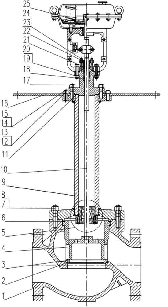
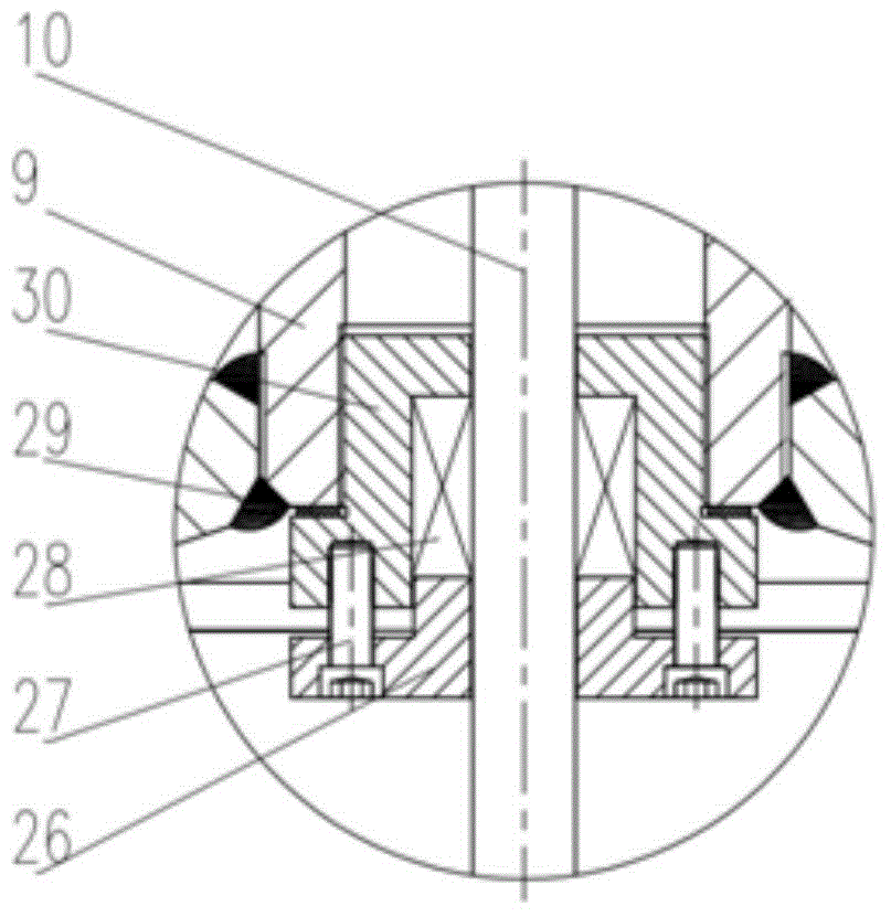
[0020] see figure 1 , a cryogenic control valve with piston pressure self-sealing and positioning. The valve body 1 is provided with a sleeve 3 and a metal wound gasket 2 therebetween. A valve plug 4 is arranged inside the sleeve, and the upper part of the valve plug is connected with the lower part of the valve stem 10 . The bottom of the extended bonnet 9 is provided with a piston pressure self-sealing and positioning assembly 5, which is connected with the internal thread at the lower end of the extended bonnet by its upper thread. The extended valve cover 9 arranged on the upper part of the valve body is fixed by bolts 7 and nuts 8 fasteners, and the sealing gasket 6 and the sleeve are compressed therebetween. An isolation drip pan 16 and an upper valve cover 17 are provided above the extended valve cover, which are respectively connected and fixed...


PUM


Abstract

A deep refrigeration regulating valve with the piston pressure self-sealing and positioning functions comprises a valve body, a lower valve cover, a lengthened valve cover, a valve rod, an executing mechanism and the like. A sleeve is arranged inside the valve body, a valve piston is arranged inside the sleeve, the upper portion of the valve piston is connected with the lower portion of the valve rod, the lengthened valve cover is arranged at the upper portion of the valve body, a piston pressure self-sealing and positioning assembly is arranged at the lower portion of the lengthened valve cover, and an upper thread of the piston pressure self-sealing and positioning assembly is connected with an internal thread at the lower end of the lengthened valve cover. An isolation drip tray and an upper valve cover are arranged on the lengthened valve cover. The upper valve cover is internally provided with sealing packing and is pressed through a packing bushing and a packing gland. The executing mechanism is arranged at the upper portion of the upper valve cover. The valve rod penetrates through the upper valve cover, the lengthened valve cover and the piston pressure self-sealing and positioning assembly. The lower portion of the valve rod is connected with the valve piston, and the upper portion of the valve rod is connected with the executing mechanism. The piston packing plays a role in soft positioning and prevents cracks, fractures and hard-positioning pull injuries, all of which are caused by bending of the lengthened valve rod, and it is guaranteed that the valve opening, closing and adjusting actions are reliable, the valve is sealed reliably and the system is safe and reliable.

Description

technical field [0001] The invention relates to a cryogenic regulating valve, in particular to a cryogenic regulating valve with piston pressure self-sealing and positioning. Background technique [0002] Cryogenic regulating valves play a very important role in the automatic control of the process of modern liquefied natural gas, liquid oxygen, liquid hydrogen, liquid helium, etc. In this process control, it is necessary to open and close and adjust the circulation parameters of the medium according to the real-time data signal. Sensitivity, reliability, sealing and life between valve stem and packing are crucial for control action. Because the lower section of the valve stem in the bonnet of the cryogenic regulating valve is connected to the valve core, and the upper section cooperates with the sealing packing in the sealing box to extend out to connect with the actuator, the cryogenic medium in the space in the bonnet communicates with the valve body, and the valve The ...

Claims


Application Information

Patent Timeline
Patent Type & Authority Applications(China)
IPC IPC(8): F16K1/00F16K1/32F16K41/02F16K49/00F16L59/16
Inventor 陈源金升扬
Owner HUBEI TAIHE PETROCHEM EQUIP
Learn More