
Separation type gas-control high-temperature pulse valve

A pulse valve, separation technology, applied in separation methods, dispersed particle separation, valve lift and other directions, can solve the problems of short fatigue life, high cost, affecting the surrounding environment, etc., to improve temperature resistance, low manufacturing cost, improve The effect of reliability

Inactive Publication Date: 2016-03-30
CHINA NAT HEAVY MACHINERY RES INSTCO
View PDF7 Cites 8 Cited by
  • Summary
  • Abstract
  • Description
  • Claims
  • Application Information

AI Technical Summary

Problems solved by technology

At present, the types of pulse valves that can be used for high-temperature gases on the market are still very limited, far from meeting the needs of the market
Using the traditional diaphragm pulse valve, although the structure is simple, the diaphragm has poor temperature resistance and short fatigue life, which cannot meet the requirements of high-temperature gas working conditions
The structure of the traditional pulse valve also makes a small amount of blowback gas leak into the surrounding air, affecting the surrounding environment
When coal gas is used as back blowing gas, the gas leaking to the surroundings will also cause safety hazards
In addition, the high-temperature pulse cleaning valves involved in patent numbers CN103470782A and CN102032384A, due to the use of special bellows, special cylinders and stroke switch displacement controllers, etc., make the whole device large and complex in structure, and the cost is high, which is inconvenient for users to use.

Method used


Image

  • Separation type gas-control high-temperature pulse valve

Examples


Embodiment Construction

[0028] The implementation of the present invention will be described in detail below in conjunction with the drawings and examples.

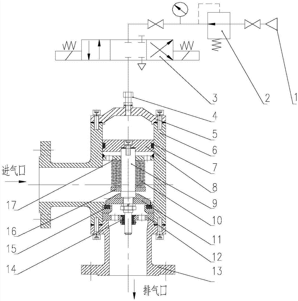
[0029] like figure 1 As shown, a separate air-controlled high-temperature pulse valve includes two separate parts. The first part is an electromagnetic reversing valve connected to the gas source, and the second part is the pulse valve body. The two parts are connected by a gas pipeline. The separate structure can weaken the impact of the high temperature pulse valve body on the solenoid valve, and the two can be installed separately at a certain distance.

[0030] The pulse valve body mainly includes end cover 5, valve body 6, seal 7, piston 8, piston rod 9, disc spring group 10, gland 11, support 12, exhaust flange 13, graphite bearing 14, seal Ring 15, baffle plate 16 and support plate 17.

[0031] The piston 8, the piston rod 9, the disc spring group 10, the gland 11 and the like form a piston assembly, and the entire piston assembly can m...


PUM


Abstract

The invention provides a separation type gas-control high-temperature pulse valve which is composed of a solenoid electric valve and a pulse valve body. The pulse valve body comprises a valve body, a piston assembly and a sealing assembly. The valve body is provided with an injected gas inlet, an injected gas outlet and a control port. The gas control port is connected with the solenoid electric valve through a gas pipeline. The injected gas outlet is opposite to the gas control port. The piston assembly is located in the valve body and comprises a piston rod. One end of the piston rod is connected with a piston, and the other end of the piston rod is connected with one side of a gland. The sealing assembly is located in the valve body and comprises a sealing ring. The piston is located between the gas control port and a supporting plate. The piston rod penetrates the supporting plate. The other side of the gland is the injected gas outlet. The sealing ring seals the portion between the gland and the injected gas outlet. The injected gas inlet is located between the gland and the supporting plate. According to the separation type gas-control high-temperature pulse valve, the spraying and blowing work is achieved by alternately attaching the contact face of the gland to the contact face of the sealing ring and separating the contact face of the gland from the contact face of the sealing ring, the process is controlled through reciprocating movement of the piston assembly, the influence on the solenoid electric valve by heat conduction is weakened, and the reliability of work is improved.

Description

technical field [0001] The invention belongs to the technical field of high-temperature dust removal, and in particular relates to a separate air-controlled high-temperature pulse valve. Background technique [0002] With the continuous improvement of domestic environmental protection standards and related process requirements, high-temperature dust removal technology is becoming more and more common in the coal chemical industry, metallurgy, nonferrous metals and other industries. The high temperature gas pulse valve is a very important part of the filter tube type high temperature gas dust removal system, and its performance and reliability have a decisive impact on the performance of the whole machine. Especially in the medium and low temperature pyrolysis process system of coal, in order to make the tar obtained have higher purity, it is necessary to filter out the solid particles in the high temperature pyrolysis gas in advance. When using a filter tube type high-tempe...

Claims


Application Information

Patent Timeline
IPC IPC(8): F16K1/00F16K27/02F16K31/122F15B15/22B01D46/42
CPCF16K1/00B01D46/4272F15B15/226F16K27/02F16K31/122
Inventor 赵玉良张帆佟占胜王宇航李俊辉葛东辉李勇鹏
Owner CHINA NAT HEAVY MACHINERY RES INSTCO
Learn More