Double-temperature refrigerating and heating system
A heating system, medium temperature technology, applied in the direction of refrigerator, refrigeration and liquefaction, heating and refrigeration combination, etc., can solve the problem of switching between suction and exhaust ports, and achieve the effect of improving energy efficiency
- Summary
- Abstract
- Description
- Claims
- Application Information
AI Technical Summary
Problems solved by technology
Method used
Image
Examples
Embodiment 1
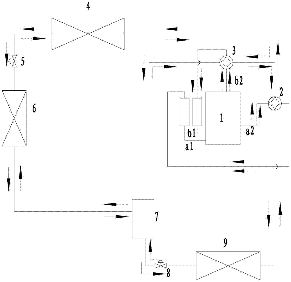
[0039] image 3 This is a schematic diagram of the cycle of the dual-temperature refrigeration and heating system provided in the first embodiment of the present invention. like image 3 As shown, the first dual-temperature refrigeration and heating system proposed in this embodiment includes a low-temperature cooling system consisting of a compressor 1, a four-way valve, a throttle valve, an outdoor heat exchanger 4, a gas-liquid separator and an indoor heat exchanger. Evaporation circuit and medium temperature evaporation circuit. The indoor heat exchanger includes a first-stage indoor heat exchanger 6 and a second-stage indoor heat exchanger 9, one of the indoor heat exchanger and the outdoor heat exchanger 4 is a condenser, and the other is an evaporator. The four-way valve includes a first four-way valve 2 and a second four-way valve 3 . The compressor 1 includes a first cylinder and a second cylinder, a first cylinder, a first four-way valve 2, a first-stage throttle ...
Embodiment 2
[0047] This embodiment proposes a second dual-temperature refrigeration and heating system. The structure of the dual-temperature refrigeration and heating system in this embodiment is basically the same as that of the system described in the first embodiment. The differences are:
[0048] like Figure 5 As shown, a first solenoid valve 10 and a second solenoid valve 11 are added to the dual-temperature refrigeration and heating system of this embodiment. Specifically, the first solenoid valve 10 is installed in the connection between the flasher 7 and the second-stage indoor heat exchange On the pipeline of the heat exchanger 9, the outdoor heat exchanger 4 is connected with the second-stage indoor heat exchanger 9 through a pipeline, and a second solenoid valve 11 is installed on the pipeline. The purpose of adding the first solenoid valve 10 and the second solenoid valve 11 is to prevent the two-way exhaust gas from entering the flasher 7 for mixing during heating operation...
Embodiment 3
[0051] This embodiment proposes a third dual-temperature refrigeration and heating system. The structure of the dual-temperature refrigeration and heating system in this embodiment is basically the same as that of the system described in the first embodiment. The differences are:
[0052] like Image 6 As shown, the system components and cycles of this embodiment are basically the same as those described in Embodiment 1, except that the first-stage indoor heat exchanger 6 and the second-stage indoor heat exchanger 9 in Embodiment 1 are replaced by those arranged side by side. The first-stage double-row indoor heat exchanger 12 and the second-stage double-row indoor heat exchanger 13 are provided.
[0053] Specifically, during cooling, the first-stage double-row indoor heat exchanger 12 (medium-temperature row evaporator) is located on the windward side, and the supply air is cooled once, and then passes through the second-stage double-row indoor heat exchanger 13 (low-temperat...
PUM
 Abstract
Description
Claims
Application Information
 - R&D
- Intellectual Property
- Life Sciences
- Materials
- Tech Scout
- Unparalleled Data Quality
- Higher Quality Content
- 60% Fewer Hallucinations
Browse by: Latest US Patents, China's latest patents, Technical Efficacy Thesaurus, Application Domain, Technology Topic, Popular Technical Reports.
© 2025 PatSnap. All rights reserved.Legal|Privacy policy|Modern Slavery Act Transparency Statement|Sitemap|About US| Contact US: help@patsnap.com


