Tandem drying system

A drying system, series technology, applied in the direction of drying solid materials, drying gas layout, local stirring dryer, etc., can solve the problems of difficult matching and adjustment of the system, high cost of environmental protection and hidden safety hazards, etc., and achieves a simple and stable system. The effect of low cost of environmental protection and no hidden safety hazards

Active Publication Date: 2016-03-30
VERBOCA ENERGY SAVING TECH CO LTD
View PDF5 Cites 20 Cited by
  • Summary
  • Abstract
  • Description
  • Claims
  • Application Information

AI Technical Summary

Problems solved by technology

[0009] The technical problem to be solved by the present invention is to provide a tandem drying system, which can fundamentally achieve the purpose of energy saving and emission reduction, and at the same time effectively solve the problems of traditional drying systems such as difficulty in system matching and adjustment, excessive exhaust air volume, heating energy Excessive consumption, potential safety hazards, and high cost of environmental protection

Method used


Image

  • Tandem drying system
  • Tandem drying system
  • Tandem drying system

Examples


Embodiment 1

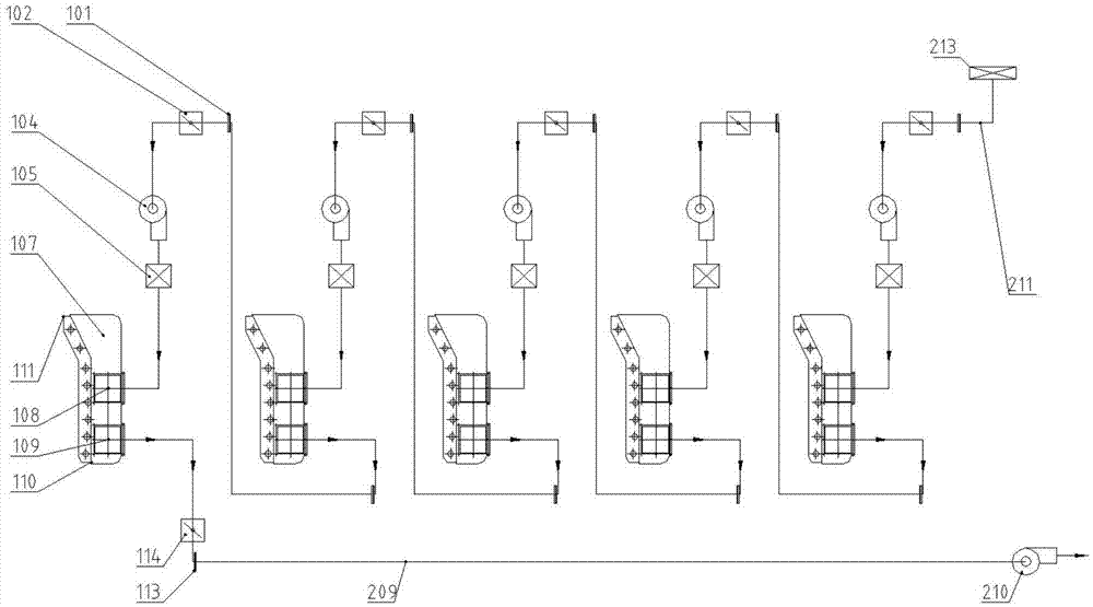
[0032] Embodiment 1: Taking the gravure printing machine as an example, see figure 1 , to describe the implementation of the series drying system:

[0033] The tandem drying system of the present embodiment includes an air supply device, an exhaust device and at least two groups of drying units; the drying unit includes a unit air supply fan 104 and a drying box 107, and the drying unit is provided with a unit air inlet 101 and a Air outlet 113, described drying box 107 is provided with drying box air inlet 108, drying box air outlet 109, drying box feed port 110 and drying box discharge port 111, described unit air inlet 101 and described drying box enter The tuyere 108 is connected, and the unit air outlet 113 is connected with the drying box air outlet 109; the exhaust device includes an exhaust main pipe 209, and the exhaust main pipe 209 is provided with the unit air outlet of the last group of drying units 113 connected exhaust air inlet (the exhaust air inlet and the u...

Embodiment 2

[0041] Embodiment 2: Taking the gravure printing machine as an example, see image 3 , to describe the implementation of the tandem drying system for centralized air suction and centralized air supply from the bottom of the printing unit:

[0042] As in the serial drying system described in Embodiment 1 and the improved Embodiment 1, the main air supply pipe 211 simply and directly enters the air directly from the external environment of the system, while in Embodiment 2, it also has the ability to take into account the leakage of the exhaust gas of the printing unit or the ink tank The air intake form of volatile solvent waste gas exhaust is centralized air supply. On the basis of the above-mentioned embodiment 1, the air supply device also includes an air supply fan 212 and at least two air collecting grooves 215, and the air supply main pipe 211 is provided in parallel with a plurality of air supply inlets corresponding to each group of drying units one by one. , the air c...

Embodiment 3

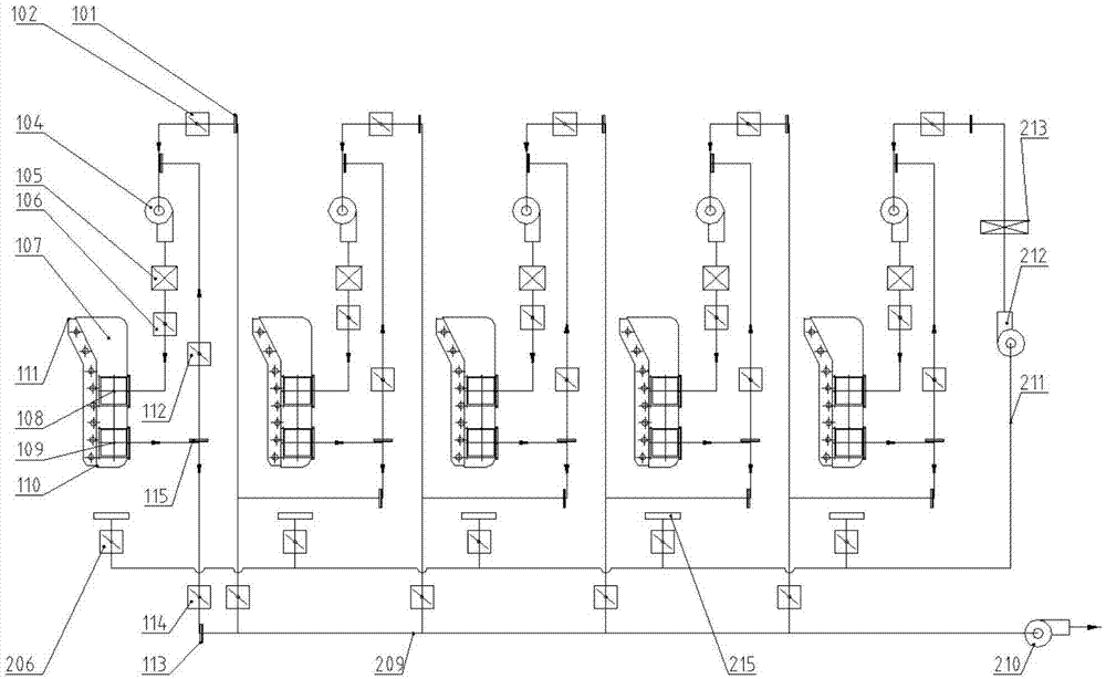
[0043] Embodiment 3: Take the dry laminating machine as an example, see Figure 4 , to explain the central heating of the series drying system:

[0044] Compared with Embodiment 1, the main difference is that: the air supply device can also use the hot air main pipe 207 to centrally supply hot air to several drying units after external heating, that is, on the basis of the above-mentioned embodiment 1, the air supply device It also includes a hot blast main pipe 207, an air supply fan 212, a hot blast stove 216, an air supply filter 213, and at least two hot blast valves 103; the hot blast main pipe 207 is provided in parallel with a plurality of hot air outlets corresponding to each group of drying units one by one. The hot air outlets are respectively connected to the unit air inlets 101; the hot air valve is arranged between the hot air outlets and the unit air inlets 101; On the header section of the hot blast inlet side of the hot blast main pipe 207. Thus, the air inle...


PUM


Abstract

The invention provides a tandem drying system. The tandem drying system comprises at least two drying units, wherein each drying unit comprises a unit air supply fan and a drying box; a unit air inlet and a unit air outlet are formed in each drying unit; a drying box air inlet and a drying box air outlet are formed in each drying box; each unit air inlet is connected with the corresponding drying box air inlet; each unit air outlet is connected with the corresponding drying box air outlet; an exhaust air inlet which is connected with the unit air outlet of the last drying unit is formed in an exhaust air header pipe; a supply air outlet which is connected with the unit air inlet of the first drying unit is formed in a supply air header pipe; in every two adjacent drying units, the unit air outlet of the former drying unit is connected with the unit air inlet of the latter drying unit; each unit air supply fan is arranged between the corresponding unit air inlet and the corresponding drying box air inlet; and an exhaust air fan is arranged on the exhaust air outlet of the exhaust air header pipe. The tandem drying system has the advantages of simplicity and stability, easiness in adjustment, small exhaust air amount, low energy consumption, no potential safety hazards, low environment protection cost and the like.

Description

technical field [0001] The invention belongs to the technical field of energy saving and emission reduction, and relates to a multi-unit hot air drying process in industries such as packaging and printing, coating and coating, and is specifically applied to production equipment requiring hot air drying such as gravure printing machines, compound machines, coating machines, and furniture spray paints. . Background technique [0002] The drying system is the main energy consumption unit of printing, compounding, coating, spraying and painting production equipment, and it is also the main emission source of exhaust gas. The efficiency of the drying system is the core parameter of the production equipment performance evaluation index. [0003] At present, the drying system of most production equipment does not have a good automatic control function. During operation, the operator relies on the operator to manually adjust the operating state of the drying system based on practica...

Claims


Application Information

Patent Timeline
Patent Type & Authority Applications(China)
IPC IPC(8): F26B9/06F26B25/00F26B21/00B41F23/04B05D3/04
CPCB05D3/0413F26B9/06F26B21/001F26B21/003F26B21/004F26B25/005
Inventor 段元敏简甦
Owner VERBOCA ENERGY SAVING TECH CO LTD
Why Eureka
Try Eureka