Modular H bridge cascade multi-level power electronic transformer control system

A cascading multi-level, power electronics technology, applied to electrical components, AC power input conversion to AC power output, AC power input conversion to DC power output, etc., can solve the problem of automatic mutual balance of three-phase power , can not meet the problems of fault ride-through control, unsatisfactory dynamic response performance, etc., and achieve the effect of good dynamic response performance, reduced adjustment time and overshoot, and reduced complexity

Inactive Publication Date: 2016-03-30
CHINA ELECTRIC POWER RES INST +2
View PDF4 Cites 17 Cited by
  • Summary
  • Abstract
  • Description
  • Claims
  • Application Information

AI Technical Summary

Problems solved by technology

However, the current controllers of these power electronic transformers have complex structures, do not have the ability to automatically balance the three-phase electric energy at all lev

Method used


Image

  • Modular H bridge cascade multi-level power electronic transformer control system
  • Modular H bridge cascade multi-level power electronic transformer control system
  • Modular H bridge cascade multi-level power electronic transformer control system

Examples


example 1

[0032] The present invention is specifically introduced below in conjunction with accompanying drawing:

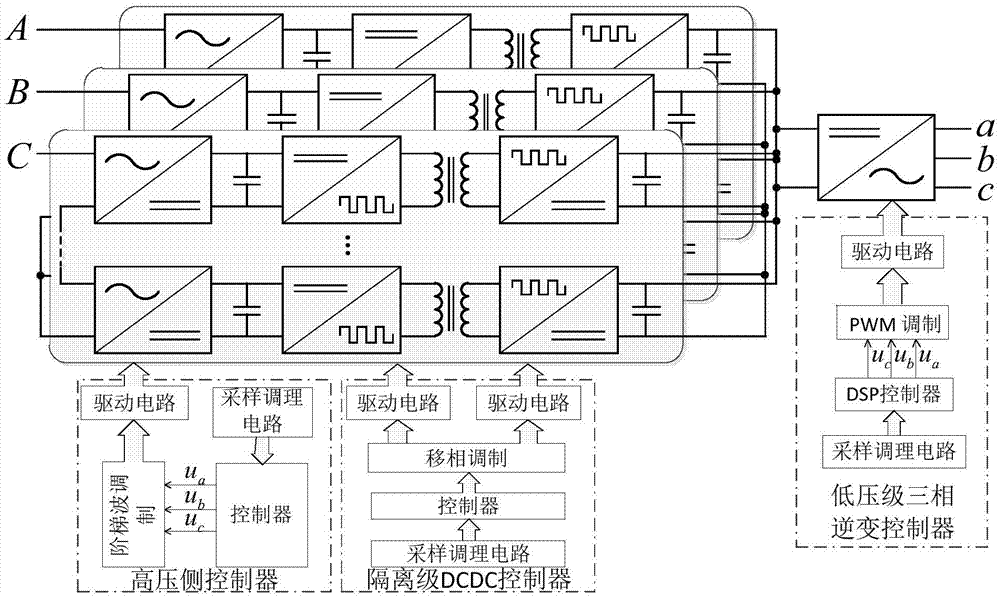
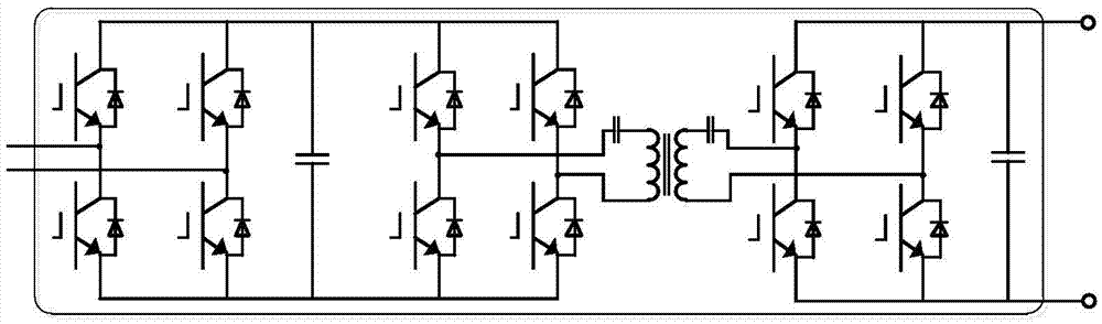
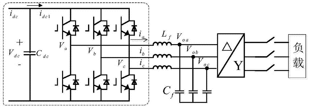
[0033] like figure 1 As shown, the modularized H-bridge cascaded multi-level power electronic transformer control system provided in this example, its system structure includes: a high-voltage stage rectifier circuit unit composed of multiple single-phase H-bridge rectifiers cascaded connected to the three-phase input grid 1. An isolation-level conversion circuit unit composed of multiple high-frequency DC / DC isolation converters connected in parallel to the number of single-phase H-bridge rectifiers. The hardware topology diagram of a single high-voltage rectifier circuit and isolation-level conversion circuit is as follows figure 2 As shown, the low-voltage inverter circuit unit connected to the output terminal of the isolation stage conversion circuit unit, its hardware topology diagram is as follows image 3 As shown, and the high-voltage side controller, the isolati...

example 2

[0058] In order to verify the performance of the high-voltage stage rectifier circuit unit in the control system provided by the present invention, in this example, the input of phase A voltage and phase B voltage is stable, and the voltage of phase C drops by 50% in 0.2s. The system is controlled, wherein, the A-phase reference voltage value waveform and the actual output capacitor voltage waveforms of each single-phase H-bridge rectifier in the A-phase are respectively as follows Figure 7 ~ Figure 8 Shown:

[0059] see Figure 7 , the reference voltage value of phase A is 10kV before 0.2s, and 12kV after 0.2s, it can be seen from the waveform that the DC voltage of each phase can track the reference value well;

[0060] see Figure 8 , the actual value of each single-phase H-bridge rectifier in phase A is about 630V before 0.2s, and about 800V after 0.2s. It can be seen that each single-phase H-bridge rectifier has better balance.

example 3

[0062] In order to verify the performance of the isolation level conversion circuit unit in the control system provided by the present invention, the system controls the system under the condition that the isolation level conversion output is set at 800V, and the bus voltage waveform at the output end of the high frequency DC / DC isolation converter like Figure 9 Shown: The bus voltage at the output end of the high-frequency DC / DC isolation converter stabilizes at 700V before 0.2s, and at 800V after 0.2s. It can be seen that the bus voltage at the output end can quickly track the reference value.


PUM


Abstract

The invention discloses a modular H bridge cascade multi-level power electronic transformer control system, comprising a high-voltage rectifier circuit unit composed of a plurality of cascade single-phase H bridge rectifiers, an isolated converter circuit unit composed of a plurality of parallel high-frequency DC/DC isolated converters correspondingly connected with the single-phase H bridge rectifiers, a low-voltage inverter circuit unit connected to the output end of the isolated converter circuit unit, as well as a high-voltage side controller, an isolation level controller and a low-voltage inverter controller which are separately used for controlling the above units, wherein the controllers independently control the high-voltage rectifier circuit unit, each high-frequency DC/DC isolated converter and the low-voltage inverter circuit unit by adopting a high-voltage rectifier control module, an isolated double-loop control module and a double-loop inverter control module separately. The system simplifies the design of the controllers, and the stability and the reliability of the transformer control system are improved.

Description

technical field [0001] The invention relates to the technical field of power electronics, in particular to a power electronic converter system. Background technique [0002] Power electronic transformer is also called solid-state transformer or flexible transformer. It is a new type of transformer based on power electronic conversion technology and electromagnetic induction technology. It completely changes the system structure of traditional transformers. On the basis of basic functions such as electrical isolation and energy transfer, it can also realize many additional functions such as bidirectional power flow control and power quality control. It is the key equipment for the construction of the next generation of smart grid. The current power electronic transformer has a variety of topological structures, which generally include three parts: high voltage level, isolation level and low voltage level. Among them, the high voltage level generally adopts a cascaded multi-le...

Claims


Application Information

Patent Timeline
IPC IPC(8): H02M5/458H02M7/5387H02M7/49
CPCH02M5/4585H02M7/49H02M7/5387
Inventor 段青施永苏建徽史常凯马春艳李玉凌胡博刘君门志勇刘南
Owner CHINA ELECTRIC POWER RES INST
Why Eureka
Try Eureka