Clamping mechanism and process flow of heat sink of aluminum alloy transformer

A technology of clamping mechanism and heat sink, which is applied in the direction of metal processing equipment, manufacturing tools, auxiliary devices, etc., can solve the problems of reduced heat dissipation efficiency of heat sink, increased welding difficulty, and unstable chemical properties of metal iron, etc., to reduce bending deformation risk, solve the phenomenon of bending deformation, and the effect of simple and reliable overall processing

Inactive Publication Date: 2018-03-02
ZIBO DINGDIAN ELECTRICAL EQUIP CO LTD
View PDF7 Cites 0 Cited by
  • Summary
  • Abstract
  • Description
  • Claims
  • Application Information

AI Technical Summary

Problems solved by technology

[0004] (1) Most of the existing transformer heat sinks are made of iron materials, and the chemical properties of metallic iron are not stable enough, easy to oxidize, and iron is easy to absorb infrared rays, resulting in a decrease in the heat dissipation efficiency of the heat sink;
[0005] (2) Most of the existing heat sinks of transformers use connection plates to connect the oil chamber and heat sinks to form oil circuits. Difficulty, it also causes the oil chamber to bend and deform, and even oil leakage occurs;
[0006] (3) Existing transformer heat sinks need to use a variety of welding guns during processing, such as rotary welding guns, seam welding guns, oil chamber welding guns, etc., which increases the welding cost; at the same time, the clamping and positioning of the cooling fins is not reasonable in the process of processing The design of the heat sink leads to local bending and deformation after the heat sink is welded

Method used


Image

  • Clamping mechanism and process flow of heat sink of aluminum alloy transformer
  • Clamping mechanism and process flow of heat sink of aluminum alloy transformer
  • Clamping mechanism and process flow of heat sink of aluminum alloy transformer

Examples


Embodiment Construction

[0048] Below in conjunction with accompanying drawing and embodiment the present invention will be further described:

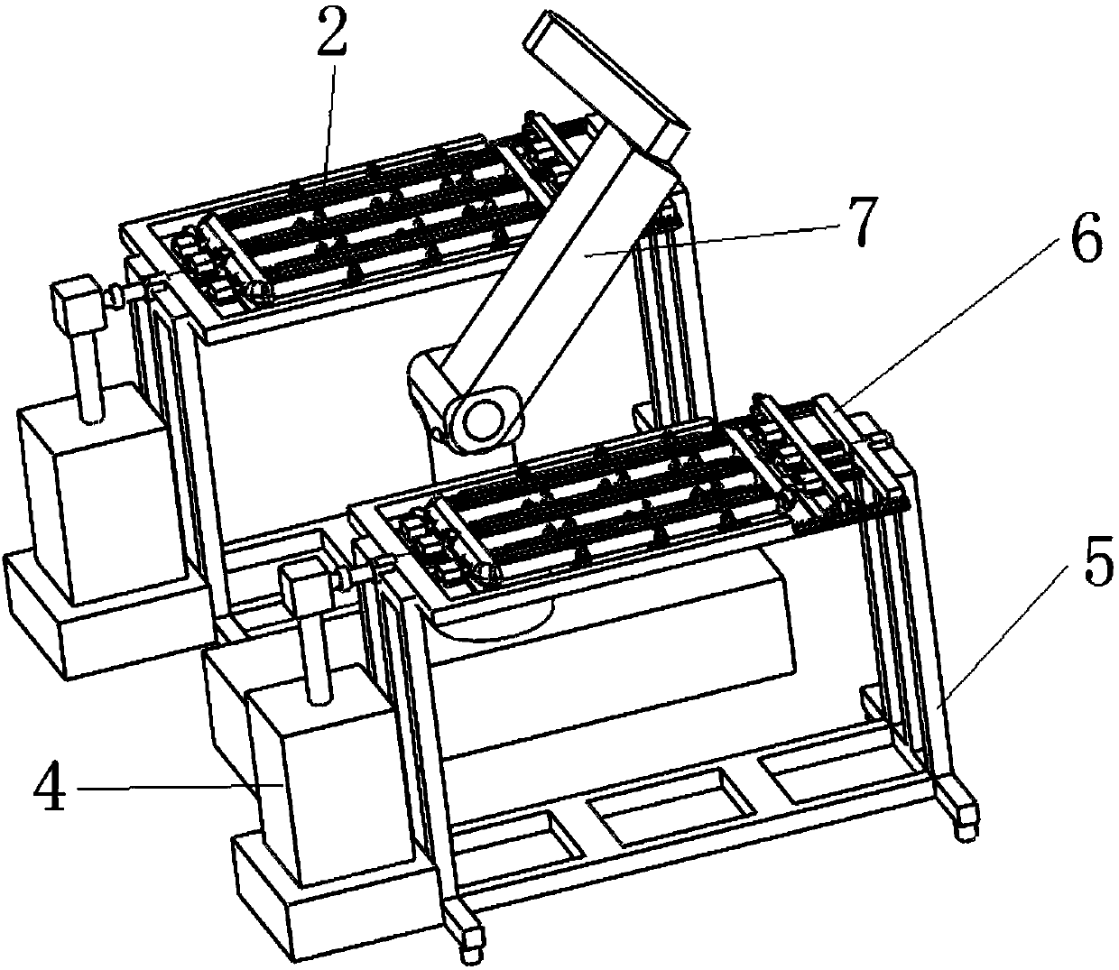
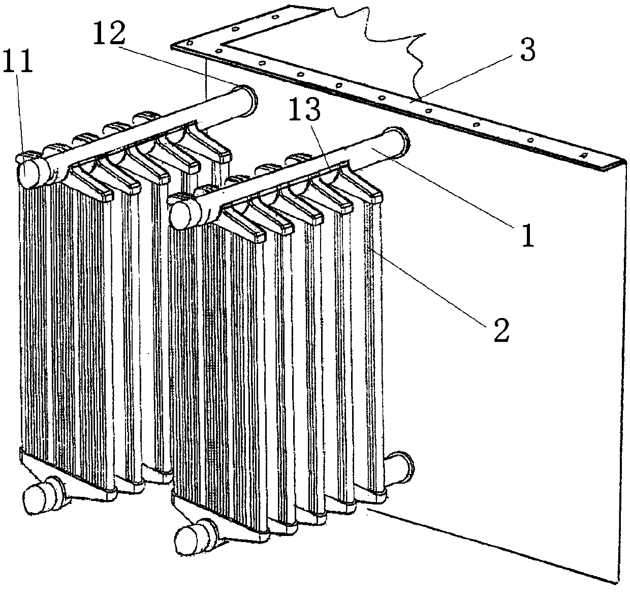
[0049] Such as figure 1 As shown, a clamping mechanism of an aluminum alloy transformer heat sink includes a fixed bracket 5; a rotating bracket 6 is installed on the fixed bracket 5; the rotating bracket 6 is connected with the turning mechanism 4; The sheet 2 is connected to the main flow pipe 1; the main flow pipe 1 is connected to the transformer 3; the transformer heat sink 2 is welded by a six-degree-of-freedom welding robot 7; the six-degree-of-freedom welding robot 7 welds two sets of transformer heat sinks 2 at the same time.

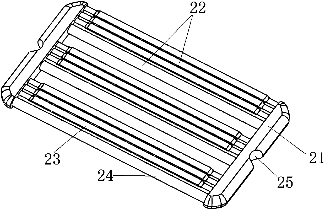
[0050] Such as figure 2 and image 3As shown, the transformer radiator 2 includes several radiator units 22 and oil chambers 21; the radiator unit 22 includes several T-shaped radiator fins 23 and longitudinal passages 24; the two ends of the radiator unit 22 are respectively connected with the oil chamber 21; Chamber 21 i...


PUM


Abstract

The invention discloses a novel aluminum alloy transformer cooling fin clamping mechanism and a technological process. The novel aluminum alloy transformer cooling fin clamping mechanism comprises fixed supports, a rotating support is installed on each fixed support and connected with a turning mechanism, a transformer cooling fin is installed on each rotating mechanism and connected with a main circulation pipeline, the transformer cooling fins are welded through a six-degree-of-freedom welding robot, and the six-degree-of-freedom welding robot conducts welding on the transformer cooling fins simultaneously; oil chambers are directly connected with the main circulation pipeline by omitting a connecting plate, and the risk of welding bending deformation of oil chambers is reduced; by means of design of the transformer cooling fin clamping mechanism, the problem that due to the fact that clamping and positioning are poor, bending deformation of the oil chambers and / or the cooling fins occurs in the welding process of the transformer cooling fins is solved; by means of the six-degree-of-freedom welding robot, the speed and precision of welding are increased; by means of design of the technological process of the transformer cooling fins, machining of the transformer cooling fins is easier and more reliable.

Description

technical field [0001] The invention relates to the technical field of transformer cooling fins, in particular to an aluminum alloy transformer cooling fin clamping mechanism and a process flow. Background technique [0002] With the rapid growth of the national economy, various high-voltage and ultra-high-voltage large-scale transformers are used more and more widely. Among them, oil-immersed power transformers use transformer heat sinks to reduce the temperature of the transformer. [0003] Although the existing transformer heat sink can reduce the temperature of the transformer to a certain extent, there are still many deficiencies in the actual use of the existing transformer heat sink, which are specifically reflected in the following aspects: [0004] (1) Most of the existing heat sinks of transformers are made of iron materials, and the chemical properties of metallic iron are not stable enough and are easy to oxidize. At the same time, iron is easy to absorb infrared...

Claims


Application Information

Patent Timeline
Patent Type & Authority Patents(China)
IPC IPC(8): B23P15/26B23K37/047
CPCB23K37/047B23P15/26B23P2700/10
Inventor 仇传祯
Owner ZIBO DINGDIAN ELECTRICAL EQUIP CO LTD
Why Eureka
Try Eureka