Printing device for printing label on surface of industrial product

A technology for printing equipment and industrial products, applied in printing, typewriters, transfer materials, etc., can solve problems such as operation errors, time-consuming and laborious, space limitations, etc., and achieve the effect of simple structure, convenient use, and reduced space height.

Inactive Publication Date: 2016-04-06
XIAN YOUQING COMMERCE & TRADE CO LTD
View PDF0 Cites 2 Cited by
  • Summary
  • Abstract
  • Description
  • Claims
  • Application Information

AI Technical Summary

Problems solved by technology

Using such a marking printer, since the installation position of the control system is on the upper surface of the frame, and the marking head is integrally arranged on the lower part of the lower plane of the workbench, the height of the whole marking printer is high. When a plurality of parts are assembled into After the overall product, the space for using the marking printer is limited. At this time, when printing markings on the visible plane of the relevant parts, the above-mentioned existing marking printers cannot be used due to space and position constraints. At the same time, the above-mentioned existing marking printer also needs to use an external fixing frame to fix the frame and fix the product at the same time, which has the disadvantage of being inconvenient to use; To modify a good mark number, the use of the above mark printer is also limited by space and location, and it cannot be directly modified. Usually, it is necessary to disassemble the entire industrial product first, and after there is enough space, the existing The mark is shoveled off with a grinding wheel and ground, and then reprinted with the above-mentioned mark printer. This will cause troublesome modification of the process, time-consuming and laborious, and may even cause damage to industrial products.

Method used


Image

  • Printing device for printing label on surface of industrial product
  • Printing device for printing label on surface of industrial product
  • Printing device for printing label on surface of industrial product

Examples


Embodiment Construction

[0018] In order to further illustrate the present invention, further describe below in conjunction with accompanying drawing:

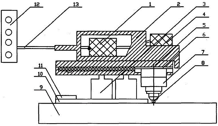
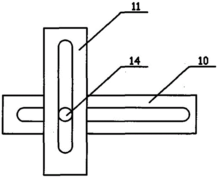
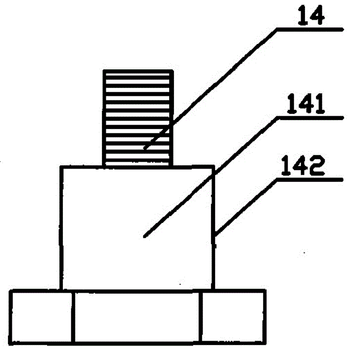
[0019] Such as figure 1 , figure 2 , image 3 , Figure 4 with Figure 5 As shown, a printing device of the present invention that prints marks on the surface of industrial products includes a control system 12 and an execution system. The control system 12 includes a controller. The control system 12 is connected to the controller separately through a cable 13. The execution system includes Frame 2, set the workbench 5 that controls the movement of the needle base 1 according to the design trajectory of the plane X direction, the workbench 5 is slidably connected to the plane Y direction relative to the frame 2, and the marking printer also includes a fixed tooling, which is formed along the plane X The positioning strip-shaped orifice plate 10 moving in the Y direction, the positioning strip-shaped orifice plate 11 moving along the plane Y dire...


PUM


Abstract

The invention discloses a printing device for printing a label on the surface of an industrial product, which comprises a control system and an execution system, and is characterized in that the control system comprises a controller; the execution system comprises a rack and a working table provided with a control pin seat. The label printer also comprises a fixing tool; the rack is internally provided with a cavity; a stepper motor is arranged in the cavity of the rack; the bottom part of the rack is provided with an electromagnet absorber; a punching head or a marking head is arranged on the pin seat in a split mode; the pin seat is fixedly arranged on the side surface of the working table; two positioning strip-shaped orifice plates movably sleeve a mounting bolt; a pin seat mounting plate is a ladder plate; the lower plate part of the ladder plate is connected with a lower plane of the working table; the upper plate part of the ladder plate is fixedly connected with the pin seat; and the mounting bolt is a bolt with four edges cut. The printing device is used for carrying out direct label printing on the surface of the industrial product and modification on the existing label content.

Description

technical field [0001] The invention relates to a printing device for printing marks on the surface of industrial products. Background technique [0002] At present, it is usually necessary to print marking numbers at appropriate positions on the surface of industrial products to record relevant information of industrial products. This method of marking information has the effect of persistent and stable information. Generally, a traditional marking printer is used to print the marking number on the surface of the relevant industrial product parts, and then the relevant parts are assembled into an overall industrial product through cooperative assembly. For example, in engine products, firstly, print the complete engine number on the visual plane of the crankcase of the engine through a traditional marking printer, and then assemble the crankcase, cylinder block, cylinder head, crankcase cover, etc. The relevant parts are assembled into a complete engine, and the relevant i...

Claims


Application Information

Patent Timeline
Patent Type & Authority Applications(China)
IPC IPC(8): B41J3/407B41J25/24
Inventor 王晓勇王雪艳
Owner XIAN YOUQING COMMERCE & TRADE CO LTD
Why Eureka
Try Eureka