Masonry arch bridge reinforced structure and construction method thereof

A technology for strengthening structures and masonry arch bridges, applied in bridge reinforcement, arch bridges, bridges, etc., can solve problems such as inability to reach a dense state, concrete pouring in, and concrete not compacted, etc., to achieve high construction efficiency, rapid construction, and good quality Effect

Active Publication Date: 2016-04-06
CHANGAN UNIV
View PDF8 Cites 11 Cited by
  • Summary
  • Abstract
  • Description
  • Claims
  • Application Information

AI Technical Summary

Problems solved by technology

If ordinary concrete is poured on the lower edge of the original arch ring, since the generally thickened layer is relatively thin, the formwork is curved and the steel bars are curved, the concrete pumped in will fall vertically under the action of gravity and accumulate between the steel bars and the formwork, causing the concrete It cannot be poured in at all; even if it is poured in, there will be problems of insufficient bonding
After being vibrated by the vibrator, the concrete is still not dense, and a large amount of concrete is accumulated at the gate of the formwork, which is difficult to construct
[0008] 3. The method of adding reinforced concrete hoops around the arch ring can increase the bearing capacity by increasing the cross-sectional area, but due to the large concrete area, the newly added concrete will have a large self-weight; usually only the arch ring is set in sections to reduce the concrete Dosage, however, sectionally set will cause the abrupt section to become the weak point of the reinforced arch ring
The scheme has the following three problems: 1. The steel corrugated plate vault is pushed into place, which is difficult to implement; 2. As mentioned above, the compact state required by the design cannot be achieved by using ordinary concrete filling; 3. The steel corrugated plate arch The technology of spraying mortar in the gap between the bridge arch circle and the inner circumferential surface cannot be implemented at all

Method used


Image

  • Masonry arch bridge reinforced structure and construction method thereof
  • Masonry arch bridge reinforced structure and construction method thereof
  • Masonry arch bridge reinforced structure and construction method thereof

Examples


Embodiment Construction

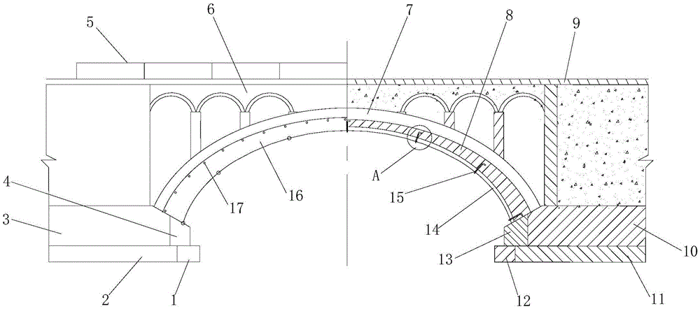
[0061] Such as figure 1 The shown reinforced structure for a masonry arch bridge includes a left widened foundation 1, a right widened foundation 12, a left widened arch base 4, a right widened arch base 13 and a corrugated steel plate arch shell 14. The left widened foundation 1 is arranged inside the left foundation 2 of the arch bridge and connected to the left foundation 2, and the right widened foundation 12 is arranged inside the right foundation 11 of the arch bridge and is connected to the right foundation 11, the left widened arch base 4 is set on the left widened foundation 1 and connected to the left arch base 3 of the arch bridge, and the right widened arch base 13 is set on the right The side widened foundation 12 is connected to the right arch 10 of the arch bridge. The corrugated steel plate arch shell 14 is arranged under the arch ring 7 of the arch bridge. The left end of the corrugated steel plate arch shell 14 is opposite to the left arch 3 Connected, the rig...


PUM


Abstract

The invention discloses a masonry arch bridge reinforced structure which comprises two side widened foundations, two side widened arch supports and a reinforced arch ring composed of self-compacting concrete and a corrugated steel arch shell. The reinforced structure can greatly enhance the bearing force of a damaged arch bridge, and the reinforcing operation has relatively small influence on mechanical properties of the existing arch ring. The invention also discloses a construction method of the masonry arch bridge reinforced structure, comprising the following steps: constructing the widened foundations; constructing the widened arch supports; constructing the corrugated steel arch shell; constructing sealing end plates; and constructing concrete filler. According to the construction method, by splicing the corrugated steel arch shell on an arch falsework and an extended arch support in a grouping mode, the construction of the masonry arch bridge reinforced structure can be quickly and effectively realized through traction movement and gradual positioning.

Description

Technical field [0001] The invention belongs to the technical field of masonry arch bridge reinforcement, and specifically relates to a masonry arch bridge reinforcement structure and a construction method thereof. Background technique [0002] With the increase of service life, under the effects of river erosion, corrosion, and weathering of the external environment, a considerable number of masonry arch bridge arch bridges such as the main arch ring, abdominal arch ring and other components have been damaged, resulting in a decrease in bearing capacity. At the same time, with the increase of the actual passing load of the existing bridges, a large number of old arch bridges can no longer meet the requirements of use, and need to increase the bearing capacity or repair and strengthen. [0003] In bridge engineering, the stone arch bridge is a very old bridge type, and it is also one of the most important bridge types on provincial, county and township roads at this stage. In rece...

Claims


Application Information

Patent Timeline
Patent Type & Authority Applications(China)
IPC IPC(8): E01D22/00E01D4/00
CPCE01D22/00E01D4/00
Inventor 原喜忠王立鹏欧阳煜
Owner CHANGAN UNIV
Why Eureka
Try Eureka