Mixer used for exhaust facility and SCR system

A mixer and facility technology, applied in the field of tail gas treatment, can solve the problems of easy crystallization, uneven distribution of reducing agent, low efficiency of selective catalytic reduction reaction, etc. The effect of reducing the risk of crystallization

Active Publication Date: 2016-04-06
WEICHAI POWER CO LTD
View PDF9 Cites 7 Cited by
  • Summary
  • Abstract
  • Description
  • Claims
  • Application Information

AI Technical Summary

Problems solved by technology

[0009] The technical problem to be solved by the present invention is: the problem of low efficiency of selective catalytic reduction reaction caused by uneven distribution of reducing agent and easy crystallization in the existing mixer

Method used


Image

  • Mixer used for exhaust facility and SCR system
  • Mixer used for exhaust facility and SCR system
  • Mixer used for exhaust facility and SCR system

Examples


Embodiment Construction

[0047] Embodiments of the present invention will be described in detail below with reference to the accompanying drawings.

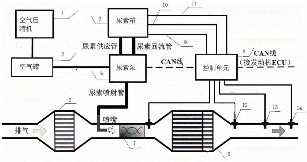
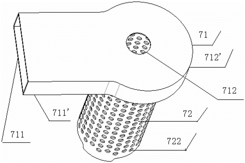
[0048] Figure 2-Figure 6 A schematic structural view of a mixer used for an exhaust facility according to an embodiment of the present invention is shown. Such as Figure 2-Figure 6 As shown, the mixer for the exhaust facility includes:

[0049] Gas cyclone 71 and liquid disperser 72;

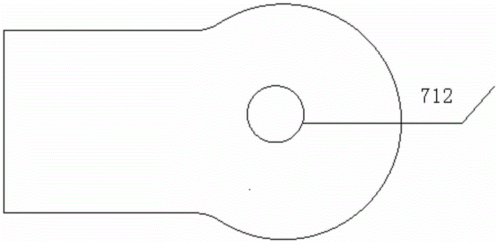
[0050] The shape of the gas swirler 71 is a shell, the gas swirler 71 includes an air inlet 711, and the gas swirler 71 is provided with a first hole 712 and a second hole 713 opposite to the direction perpendicular to the gas inlet direction;

[0051] One end of the liquid disperser 72 is vertically connected with the gas cyclone 71 through the second hole 713;

[0052] The first hole 712 of the gas cyclone 71 is used to introduce the reducing agent ejected from the nozzle;

[0053] The end of the liquid disperser 72 close to the gas swirler 71 is provided with at le...


PUM


Abstract

The invention relates to a mixer used for an exhaust facility and an SCR system. The mixer used for the exhaust facility comprises a gas cyclone and a liquid disperser. The gas cyclone is shaped like a shell and comprises a gas inlet. A first hole and a second hole which are opposite are formed in the gas cyclone in the direction perpendicular to the gas inlet direction. One end of the liquid disperser penetrates the second hole to be perpendicularly connected with the gas cyclone. The first hole of the gas cyclone is used for leading in a reducing agent sprayed out of a spray nozzle. The liquid disperser is provided with at least one blade influencing the gas flow direction. The blades are located in the gas cyclone. A plurality of through holes are formed in the liquid disperser, located outside the gas cyclone and used for dispersing the reducing agent led in by the gas cyclone. By means of the mixer, distribution of the reducing agent can be uniform, crystallization is avoided, and the efficiency of the selective catalytic reduction reaction is improved.

Description

technical field [0001] The invention relates to the field of tail gas treatment, in particular to a mixer and an SCR system for exhaust facilities. Background technique [0002] Selective Catalytic Reduction (Selective Catalytic Reduction, SCR) technology is a kind of using ammonia, ammonia water, urea or hydrocarbons as reducing agent, under the condition that the oxygen concentration is more than two orders of magnitude higher than the nitrogen oxide concentration, nitrogen Technology for reducing oxides to nitrogen. After being treated by the SCR system, the exhaust gas of the diesel engine can meet the emission regulations. The role of catalysis is to reduce the activation energy of the decomposition reaction and lower the reaction temperature to a suitable temperature range. [0003] The Selective Catalytic Reduction Converter is also known as Nitrogen Oxide Reduction (DeNO x ) catalytic converter. The most commonly used catalyst and reducing agent in automotive die...

Claims


Application Information

Patent Timeline
Patent Type & Authority Applications(China)
IPC IPC(8): F01N3/28
CPCF01N3/28F01N2610/02F01N2610/1486
Inventor 李志杰王作峰冯佳佳唐蛟高翔
Owner WEICHAI POWER CO LTD
Why Eureka
Try Eureka